Filter for wire and cable

a filter and wire technology, applied in the direction of cables, insulated conductors, conductors, etc., can solve the problems of ambient electromagnetic noise entering the electronic equipment through the electrical cables, noise may interfere with other systems, and the electronic equipment may generate electromagnetic noise during operation, etc., to achieve the effect of small diameter and high flexibility of microwires

Inactive Publication Date: 2001-11-22
ADVANCED FILTERING SYST
View PDF0 Cites 94 Cited by
  • Summary
  • Abstract
  • Description
  • Claims
  • Application Information

AI Technical Summary

Benefits of technology

0029] The microwire-coated wire is flexible, because of the very

Problems solved by technology

Electronic systems may generate electromagnetic noise during their operation.
This noise may interfere with other systems.
In many cases, ambient electromagnetic noise penetrates the electronic equipment through the electrical cables.
Moreover, signals transmitted through a cable may be transmitted to other cables in that system or to other systems, thus creating an additional noise or interference.
The efficiency of such cables, however, may not be sufficient where noise protection is required between parts of a system that are connected by cables.
For example, if noise is generated in one part of an electronic equipment, the cable may transfer that noise to another part of the equipment by an electrical conduction mechanism.
Attenuation in L-C filters is a result of impedance mismatch between the source and the filter input on one side, and between the filter output and the load.
Moreover, in many cases the values of the impedance is not known, so the selection of an eff

Method used


Image

  • Filter for wire and cable
  • Filter for wire and cable
  • Filter for wire and cable

Examples


Embodiment Construction

[0040] A preferred embodiment of the present invention will now be described by way of example and with reference to the accompanying drawings.

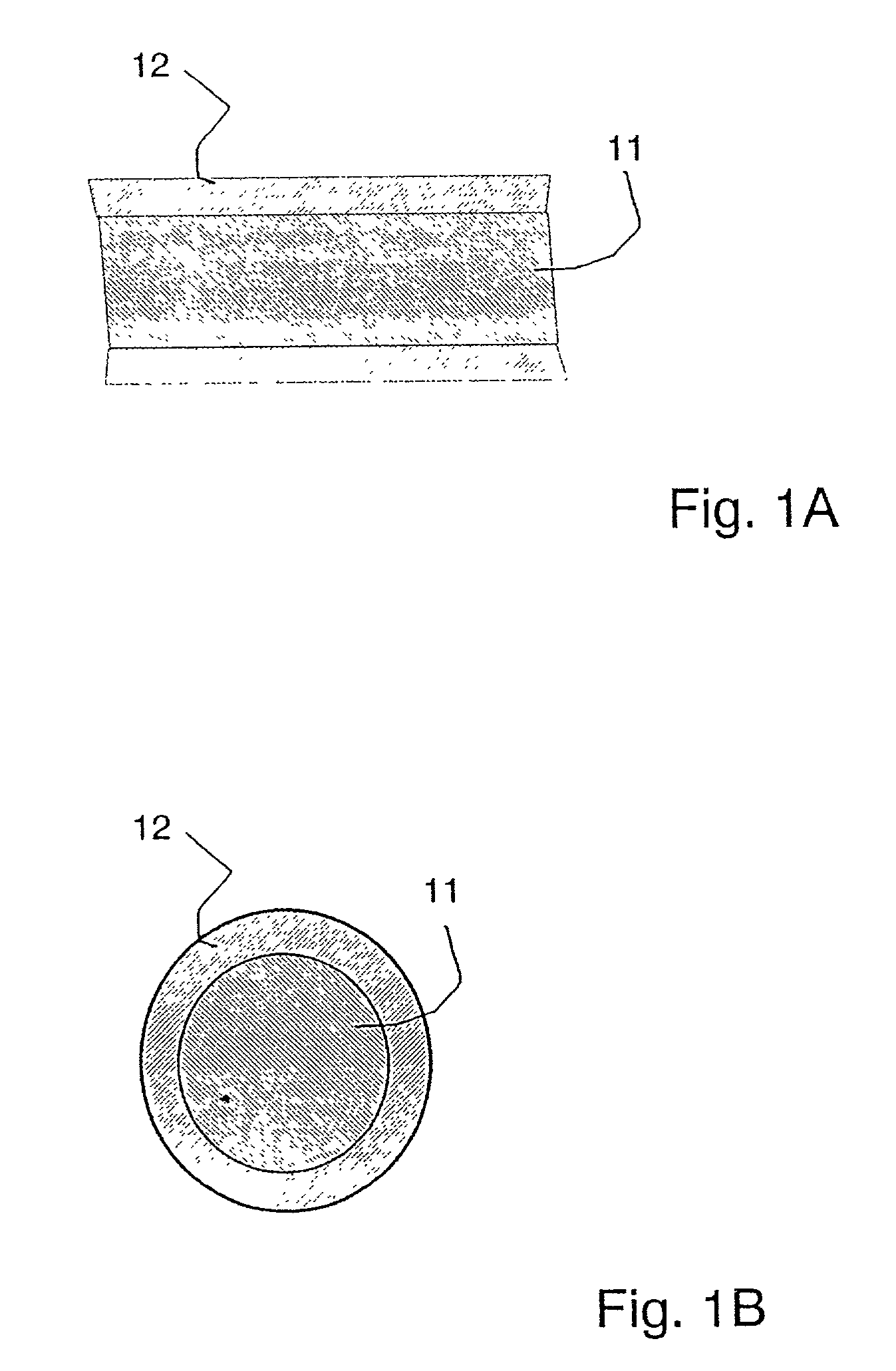
[0041] FIG. 1A illustrates a side view of a microwire, and with FIG. 1B illustrates a cross-sectional view of the microwire.

[0042] Thus, the microwire has a metallic core 11 and a glass coating 12. Microwires as illustrated are known in the art. British Patent No. 1, 120, 247 and U.S. Pat. No. 5,240,066 details a method for manufacturing microwires.

[0043] Until now, however, these microwires were not used to form EMI noise filters to protect signals transmitted along cables or wires.

[0044] In order to provide sufficient energy absorbing properties while ensuring sufficient flexibility to allow winding to form a continuous absorbing layer, a specific range of microwire dimensions is preferred, specifically, the diameter of the microwire core 11 is preferably in the range of about 6-8 microns, while the thickness of the glass coating 12 is pref...


PUM


Abstract

A filter for wires and cables comprising at least one pair of inner conductive wires made of an electrically conductive metal covered with an outer layer of magnetic absorbing material. This outer layer is formed from glass-coated microwires containing soft ferromagnetic amorphous material, preferably wound about the conductive wires to form a thin ferromagnetic layer. The filter may include two or more pairs of inner conductors with the ferromagnetic outer layers implemented separately or as a single common outer layer. The inner pairs of conductors may be either straight or twisted.

Description

[0001] This invention concern filters for wires and cables for use in electronics. The invention relates in particular to such filters which include layers of absorbing magnetic material comprising glass-coated microwires and amorphous metal tape.[0002] Prior art methods for reducing noise in electronic systems include shielding of cables and filtering.[0003] Modern electronic systems have to meet stringent requirements for Electromagnetic Compatibility (EMC). Electronic systems may generate electromagnetic noise during their operation. This noise may interfere with other systems. EMC standards and regulations for electronic equipment have been set up in many countries. These standards define a maximum level of noise that may be generated by electronic equipment, and the sensitivity of electronic equipment to noise generated by others.[0004] In many cases, ambient electromagnetic noise penetrates the electronic equipment through the electrical cables. In system comprising several pa...

Claims


Application Information

Patent Timeline
IPC IPC(8): H01B11/10
CPCH01B11/1041
Inventor MANOV, VLADIMIRANTONENCO, ALEXANDRUEXELROD, ALEXANDERRUBSHTEIN, ALEXANDERSORKINE, EVGENI
Owner ADVANCED FILTERING SYST
Why Eureka
Try Eureka