
Hybrid vehicle and process for operating a hybrid vehicle

a hybrid vehicle and hybrid technology, applied in hybrid vehicles, process and machine control, instruments, etc., can solve the problems of increasing the cost and increasing the space requiremen

Inactive Publication Date: 2001-11-22
ZF FRIEDRICHSHAFEN AG
View PDF0 Cites 9 Cited by
  • Summary
  • Abstract
  • Description
  • Claims
  • Application Information

AI Technical Summary

Benefits of technology

[0009] Instead of low-torque motors, an electric motor with a substantially higher torque than the internal combustion engine is used at low speeds. The axial structural space required by this higher torque electric motor is compensated for by a space-saving transmission, which omits a reverse gear. The forward rotational direction of the transmission input shaft and output shaft can not be changed during operation by the ICE. With the higher torque electric motor, it is possible to start movement of a vehicle using a gear that is normally used as a second gear with conventional motors. Omitting the reverse gear allows the axial structural space of the transmission to be reduced. The additional omission of the conventional first gear leads to a further reduction of the structural space of the transmission. The high torque of the electric motor, which is preferably an external rotor motor, may also be used for applying a braking force to the vehicle.

Problems solved by technology

Given the low production number of the hybrid vehicles, any required structural modification would lead to a considerably greater expense.
Therefore a problem of the prior art hybrid vehicles is to minimize the additional space requirement.

Method used


Image

  • Hybrid vehicle and process for operating a hybrid vehicle
  • Hybrid vehicle and process for operating a hybrid vehicle
  • Hybrid vehicle and process for operating a hybrid vehicle

Examples


Embodiment Construction

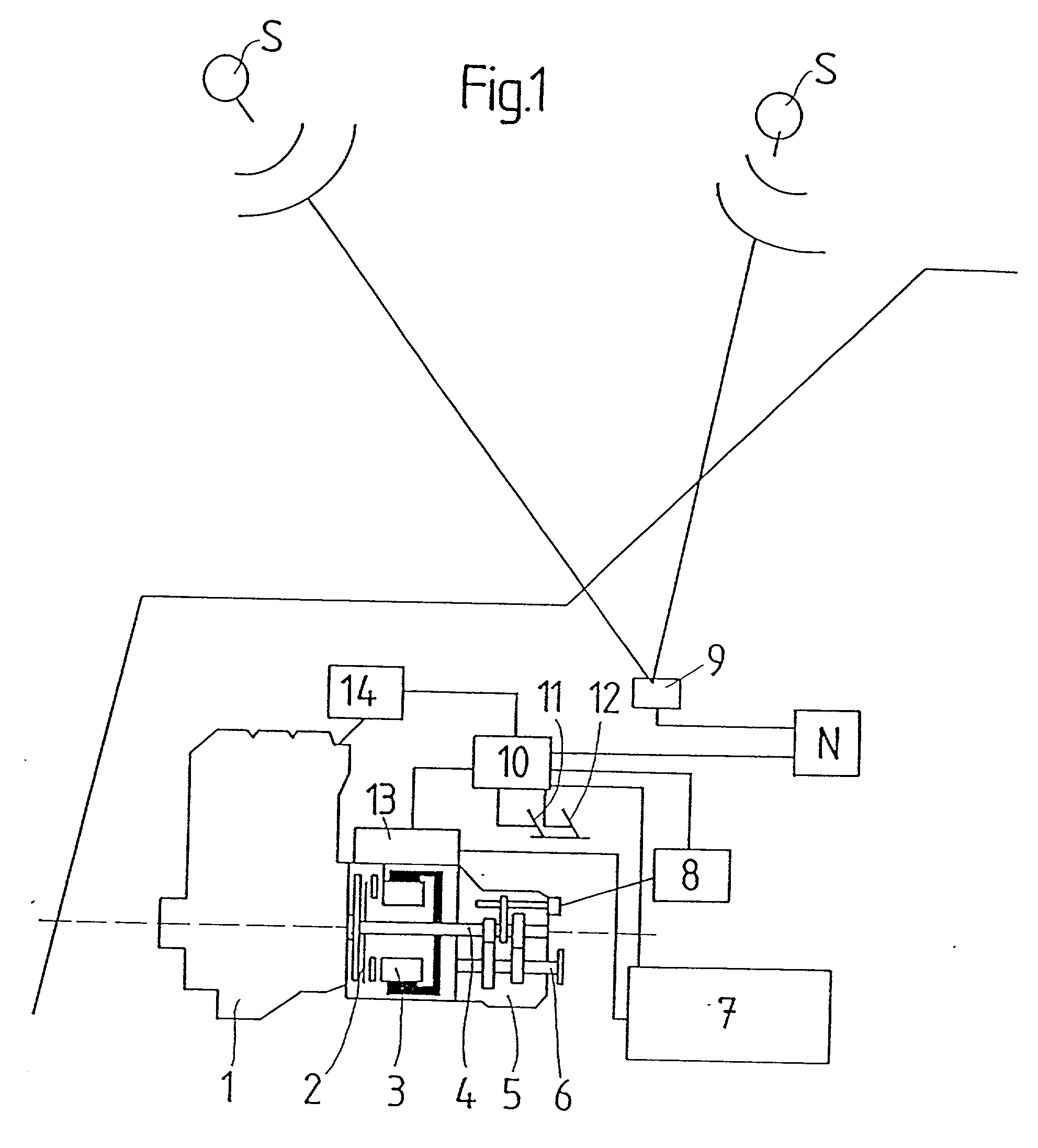
[0027] A hybrid drive according to an embodiment of the present invention includes an internal combustion engine 1 having an average output, an electric motor 3 connected to the internal combustion engine 1 via a coupling 2, and a transmission 5 flanged to the electric motor 3. The transmission 5 includes a transmission input shaft 4 and a transmission output shaft 8. An electric energy storage device 7 is connected via an intermediate connection of a power electronics system 13 to the electric motor 3 for driving the electric motor 3 with low work and high output. A vehicle computer 10 is connected to the power electronics system 13, the electric energy storage device 7, the accelerator pedal 11 and the brake pedal 12, and a motor electronics system 14 for controlling the internal combustion engine 1. The vehicle computer 10 also controls the electric motor 3 via the power electronics system 13. A transmission control 8 is also connected to the computer 10 for controlling the trans...


PUM


Abstract

A hybrid drive for a vehicle in which the driving power provided by an internal combustion engine (ICE) or an electric motor may be fed via a transmission with a transmission input shaft and a transmission output shaft to the drive train. The ICE and the electric motor are connectable to each other via a coupling and the electric motor is directly connected to the transmission. An electric energy storage device is connected to the ICE for receiving a charge and to the electric motor for providing power to the electric motor. The hybrid drive is designed so that the torque that can be provided by the electric motor is greater than that of the internal combustion engine. In addition, the transmission input shaft always turns in the same direction as the transmission output shaft so that reverse drive by the hybrid drive is only possible using the electric motor.

Description

[0001] 1. Field of the Invention[0002] The invention relates to a vehicle with hybrid drive, in which the driving power provided by an internal combustion engine or an electric motor is fed to the drive train via a transmission with a transmission input shaft and a transmission output shaft. The internal combustion engine and the electric motor are connectable to each other via a coupling. The electric motor is directly connected to the transmission. The vehicle also includes an electric energy storage device for providing power to the electric motor that is chargeable by the internal combustion engine. A process for operating a hybrid vehicle with a satellite-controlled navigation system is also disclosed.[0003] 2. Description of the Related Art[0004] A hybrid vehicle of the aforementioned type is known, for example, from references DE 43 23 601 A1 and DE 29 43 554. The reference DE 29 43 554 discloses a hybrid vehicle started by the electric motor alone. The internal combustion en...

Claims


Application Information

Patent Timeline
Patent Type & Authority Applications(United States)
IPC IPC(8): B60K6/48B60K17/04B60L50/15B60W10/02B60W10/26
CPCB60K6/48B60L2200/26B60L11/12B60L2240/62B60L2240/622B60W10/02B60W10/06B60W10/08B60W10/26B60W20/00B60W30/188B60W2550/143B60W2550/402Y02T10/6221Y02T10/6291Y02T10/7077Y02T10/7291Y02T90/16Y02T90/162Y10S903/946B60K17/04B60W50/0097B60L50/15B60W2552/20B60W2556/50Y02T10/62Y02T10/7072Y02T10/72Y02A30/30
Inventor LUTZ, DIETER
Owner ZF FRIEDRICHSHAFEN AG
Learn More