
System and method for transmitting a broadcast television signal over broadband digital transmission channels

a digital transmission channel and broadcast television technology, applied in the field of encoding and decoding video image signals, can solve the problems of data overflow, requiring significant computational power, and the speed of image decompression maintaining pace with playback, so as to reduce the size of the code, eliminate visual noise, and facilitate the marking of objects

Inactive Publication Date: 2001-11-29
FREDA ROBERT M
View PDF0 Cites 49 Cited by
  • Summary
  • Abstract
  • Description
  • Claims
  • Application Information

AI Technical Summary

Benefits of technology

[0024] It is another object of this invention to set forth coding methods by which images can be described and source-coded more efficiently for digital transmission over limited capacity channels.
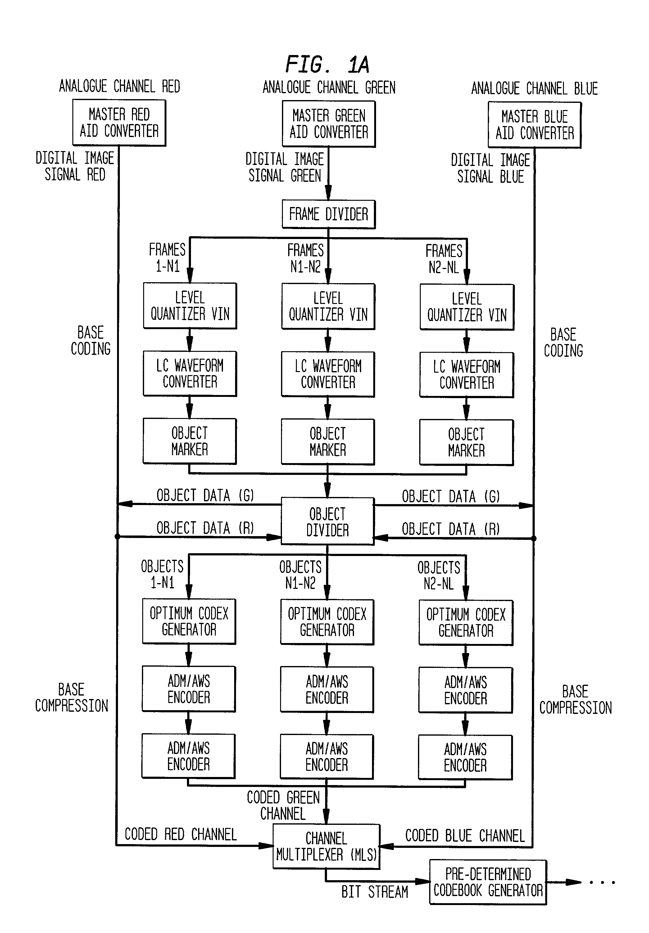
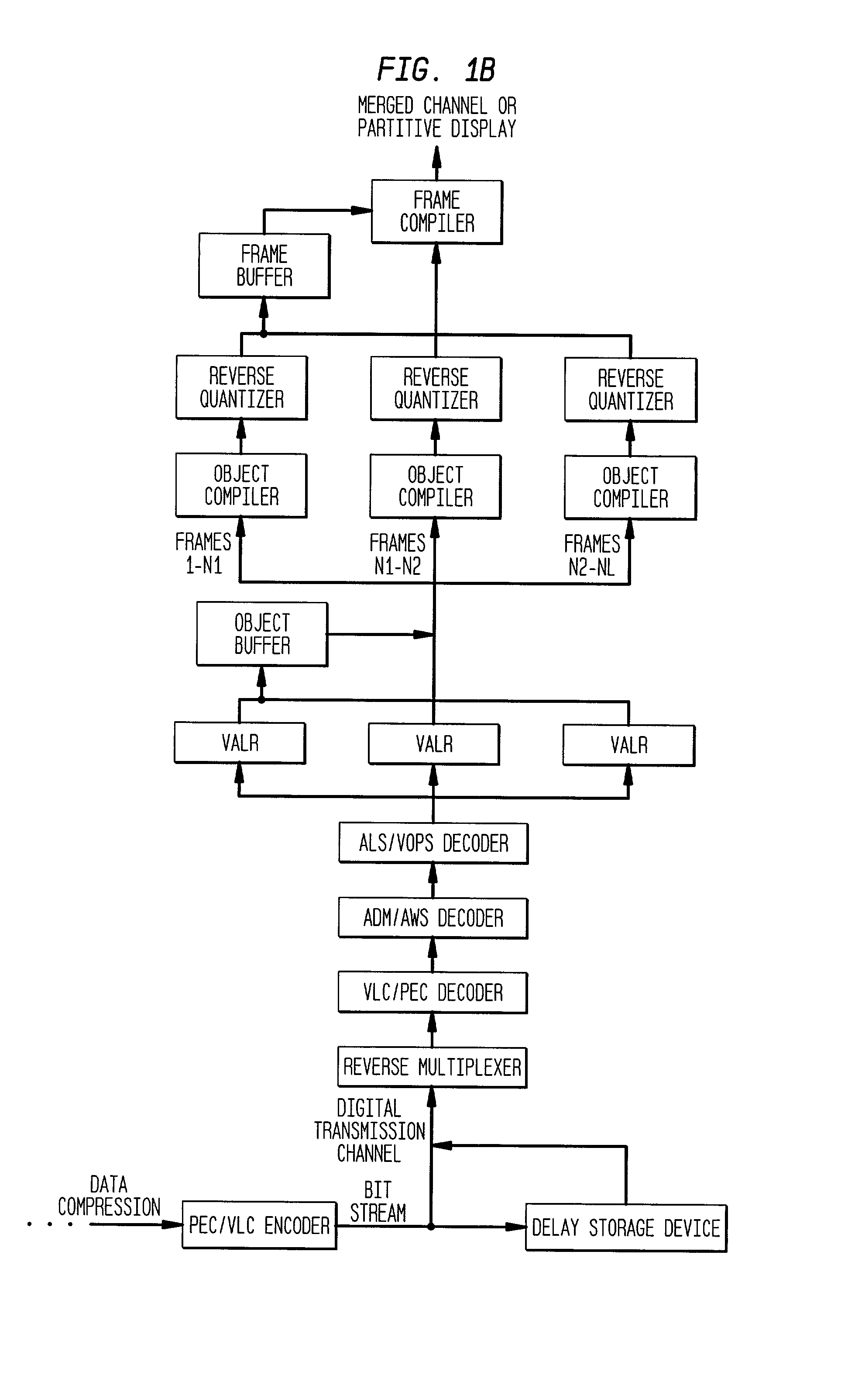
[0206] If the data rate exceeds the given channel capacity of the desired transmission method the ADM / AWS / ALS data is sent via high-bandwidth bus to a shared memory array. Dependent on the capacity overflow rate with regard to the transmission channel and the encoded image data, the encoded data is subjected to a series of lossless data compressions. If the data is intended for storage these operations are performed automatically to reduce the encoded data to a desirable storage rate. From storage, these data streams can either be transmitted directly or if bandwidth allows partially decoded prior to transmission to reduce client side computational complexity.

Problems solved by technology

Digital channel capacity is the most important parameter in digital signal transmission because insufficient channel capacity limits the amount of data that is transmittable in a given time frame.
A major technical problem in video source encoding is usually the tradeoff between the amount of compression that is required for a given channel capacity and image quality or frame rate.
Data overflow is another major problem as the bit code exceeds the capacity of the given channel.
Yet another problem is the speed of image decompression maintaining pace with playback.
This usually relates directly to the computational complexity of the encoder / decoder solution.
Also of concern is the technical problem of the variable nature of the compressed code from image to image that creates channel management problems from scene to scene within the same transmission.
Unfortunately, the Proctor et al. system and method suffers from the disadvantage of requiring significant level of computational power to perform the vector quantization of rapidly moving images, which would also tend to reduce the required bandwidth for transmission, but such methods are effective only within the limitations of vector codebooks.
While this is impressive compression, it is far from the bit rates needed to stream full screen / full rate broadcast video over low to mid bit rate channels, such as telephone lines.
Storage capacity is also an important issue with regard to image data.
On the other hand, non-uniform scalar quantization of an input signal follows the same overall procedure as the uniform quantization technique, but is often analogized to a set of stairs having unequal spacing between the steps.
The inventor has recognized that most vector and scalar quantization techniques have the same essential failing with regard to image compression and especially with regard to transmission of compressed images, in that they begin not from the visual basis and structure of the information they are attempting to reduce and reconstruct, but from the totality of the information needed to describe a given image or series of images in a specific digital format.
From a limited-channel transmission or storage perspective, this is a highly ineffective approach as it is based on a premise which accommodates mathematical structure rather than visual structures.
Highly variable rates of quality, computational complexity, frame rate playback, and frame or scene code size, all of which taken in combination or individually lead to data overflow, image degradation (blocking in the most common schemes), or decompression asynchronization and ultimately to a detractive experience on the client side.

Method used


Image

  • System and method for transmitting a broadcast television signal over broadband digital transmission channels
  • System and method for transmitting a broadcast television signal over broadband digital transmission channels
  • System and method for transmitting a broadcast television signal over broadband digital transmission channels

Examples


Embodiment Construction

: solving for buffer time required at 12 Kbytes(96,000 bits)per second

[0231] x=?

[0232] y=120 sec

[0233] z=12 Kbytes

[0234] w=2 Kbytes

[0235] m=10 fps

[0236] n=1.2 Kbytes

[0237] x=((10(2)-10(1.2))(120)) / 12

[0238] x=80 sec.

[0239] Ratio of content to advertising and sp at 12 Kbytes(96,000 bits)per second 2:3

[0240] x=?

[0241] y=120 sec

[0242] z=7 Kbytes

[0243] w=2 Kbytes

[0244] m=6 fps

[0245] n=1.2 Kbytes

[0246] X=((6(2)-6(1.2))(120) / 7

[0247] X=82 sec

[0248] Ratio of content to advertising and sp at 7 Kbytes (56,000 bits) per second=2:3

[0249] Assumption 40 K upload speed of server network content delivery system

[0250] Intro and sp sequences 8 to 15 bitmaps, 25 to 30 k

[0251] Length of intro and sp 5, 15, and 30 sec

[0252] dvj or talking heads avg. 8 to 10 frames, 25 to 30 k

[0253] length of talk 15 or 22.5 or 30 seconds

[0254] Sec Down at 40 kps

[0255] 5 200 k

[0256] 15 600 k

[0257] 22.5 900 k

[0258] 1200 k

[0259] Use choosing or any period in which user has not actually asked for content utilize time to load...


PUM


Abstract

A system and method for encoding and decoding an input video signal representative of an original moving or still image. The system includes a subsystem for low-bit rate encoding, transmission, and decoding of the moving or still image, and a server / client based buffering subsystem for receiving and decoding the encoded transmission. The client / server based buffering subsystem uses pre-cached and pre-determined content to counteract channel data overflow and create seamless viewing of the moving or still image. The encoding-decoding subsystem processes the input video signal into a format suitable for transmission and subsequent decoding be deconstructing and quantizing the signal into a waveform representing its component elementary parts according to a pre-determined luminance / chrominance gradient field or matrix of defined amplitude. The waveform is generated according to an optimally structured base code within the luminance / chrominance gradient matrix field as defined by minimum sampling rates. The waveform accurately describes the original moving or still image, within an acceptable visible variation as compared to an acceptable bit-rate for the capacity of a given transmission channel. The base code is compressed by a lossless data compression method that is dependent on transmission channel capacity limitations and / or resultant code size. The compressed command code can be transmitted to either a storage facility or to a client. If transmitted to a client, the code is decompressed into the original base code and then decoded by client-side software or hardware to reconstruct the original image within the pre-determined luminance / chrominance gradient field matrix and a pre-defined or sent coding table. The reconstructed original moving or still image can then be displayed on a video display device. Systematic use of the system and method offers a seamless viewing experience on the client side even if the size of the transmitted code exceeds the transmission channel capacity.

Description

PRIORITY DATE[0001] The applicant claims a priority date of Mar. 10, 2000 based on the filing of a provisional application by the applicant having a Ser. No. 60 / 188,215 on Mar. 10, 2000.[0002] 1. Field of the Invention[0003] The invention relates to encoding and decoding video image signals in general. In particular, the invention relates to apparatus and methods for encoding and decoding video image signals, either digital or analog, stored or live, using partitive or non-partitive image formation and pre-defined gradient fields or matrices with alternative methods of pixel description within the fields and matrices.[0004] 2. Description of the Related Art[0005] The development of digital data compression techniques for compressing visual information is very significant due to the growing demand for higher transmission capability and lower bit codes and the concomitant ability to stream video or still images through a limited capacity channel.[0006] This growing demand includes the...

Claims


Application Information

Patent Timeline
Patent Type & Authority Applications(United States)
IPC IPC(8): H04N7/26H04N7/46H04N11/04H04N21/2343H04N21/24H04N21/262H04N21/2662
CPCH04N11/042H04N21/234318H04N21/2402H04N21/26216H04N21/2662H04N19/59H04N19/186H04N19/20H04N19/436H04N19/90H04N19/30
Inventor FREDA, ROBERT M.
Owner FREDA ROBERT M
Learn More