
Liquid crystal display device and method for driving a liquid crystal display

a liquid crystal display and display device technology, applied in the direction of instruments, computing, chemistry apparatus and processes, etc., can solve the problems of increasing the consumption of electric power, reducing the memory effect, and reducing the driving speed

Inactive Publication Date: 2001-12-06
MINOLTA CO LTD
View PDF1 Cites 9 Cited by
  • Summary
  • Abstract
  • Description
  • Claims
  • Application Information

AI Technical Summary

Benefits of technology

[0011] Another object of the present invention is to provide a liquid crystal display device and a liquid crystal display driving method in which the consumption of electric power can be reduced easily.
[0012] Further, another object of the present invention is to provide a liquid crystal display device and a liquid crystal display driving method in which a high-speed drive is possible while the consumption of electric power can be reduced more.
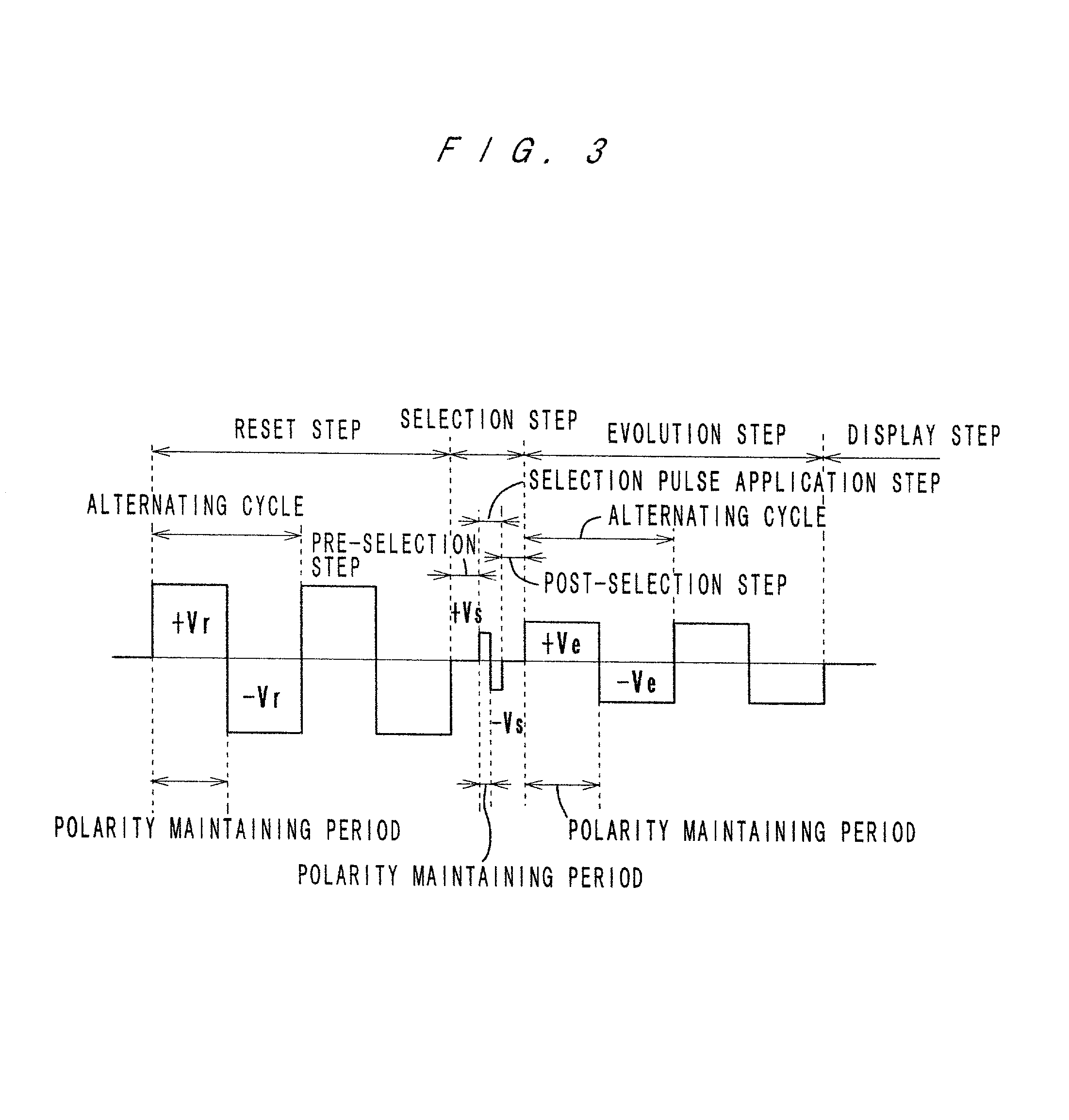
[0017] Pulse waveforms applied to the scan electrodes can be controlled independently of one another without influencing one another. In these methods, by changing the pulse waveform applied to each of the scan electrodes, the alternating cycle of the reset pulse and / or the alternating cycle of the evolution pulse is / are set longer than the alternating cycle of the selection pulse. Thereby, the number of polarity inversions in the reset step and the number of polarity inversions in the evolution step can be reduced, which results in a reduction in consumption of electric power. Also, it is not necessary to complicate the pulse waveform applied to each of the data electrodes, which is effective to suppress crosstalk.
[0018] In these methods, the alternating cycle of the reset pulse or the alternating cycle of the evolution pulse is set sufficiently long to prevent the liquid crystal from being polarized. Thereby, an exactly desired voltage acts on the liquid crystal, and degradation in display performance can be prevented. Also, the liquid crystal display can be prevented from changing its characteristics.
[0022] A liquid crystal display device according to the present invention comprises a driver which carries out one of the above-described methods. Such a liquid crystal display device achieves a reduction in consumption of electric power, suppression of crosstalk and prevention of changes of the liquid crystal display in characteristics.

Problems solved by technology

However, it is well known that such liquid crystal displays with a memory effect have a demerit that the driving speed is low.
Generally, continuous application of a DC voltage to liquid crystal causes problems such as degradation of liquid crystal molecules.
According to this prior art, however, the number of inverting the polarity of a pulse voltage applied to liquid crystal is extremely large, which increases the consumption of electric power.
The merit of providing the pre-selection step and the post-selection step is shortening the application time of the selection pulse, and this results in an increase in the driving speed.

Method used


Image

  • Liquid crystal display device and method for driving a liquid crystal display
  • Liquid crystal display device and method for driving a liquid crystal display
  • Liquid crystal display device and method for driving a liquid crystal display

Examples


example 2

Driving Example 2; See FIG. 5

[0075] A second example of matrix driving according to the driving method is described.

[0076] Waveforms applied to the scan electrodes and the data electrode shown in FIG. 5 are achieved by superimposing a voltage V1 on the respective waveforms shown in FIG. 4. In this case, the waveforms acting on the pixels are of the same waveforms as those shown in FIG. 4.

[0077] In the second example, the polarity maintaining periods of the pulses applied to each of the scan electrodes in the reset step and the polarity maintaining periods of the pulses applied to each of the scan electrodes in the evolution step are longer than the polarity maintaining period of the selection pulse acting on the pixel in the selection pulse application step. Thereby, the polarity maintaining periods of the reset waveform and the evolution waveform applied to the liquid crystal can be lengthened, and the number of polarity inversions of the reset waveform and the evolution waveform a...


PUM


Abstract

A liquid crystal display device which carries out matrix driving of a liquid crystal layer by applying AC pulses to the liquid crystal layer through a plurality of scan electrodes and a plurality of data electrodes which face and cross each other. A method of driving such a liquid crystal display comprises a reset step of applying a reset pulse to liquid crystal to reset the liquid crystal to an initial state, a selection step of applying a selection pulse to the liquid crystal to select a final state of the liquid crystal, an evolution step of applying an evolution pulse to the liquid crystal to cause the liquid crystal to evolve to the selected final state. The reset pulse and the evolution pulse have alternating cycles which are longer than that of the selection pulse, and the adjustment of the alternating cycles of the reset pulse and of the evolution pulse are made by changing the pulse waveform applied to each of the scan electrodes.

Description

[0001] This application is based on Japanese patent application Nos. 2000-158570 and 2001-136725, the contents of which are hereby incorporated by reference.[0002] 1. Field of the Invention[0003] The present invention relates to a liquid crystal display device and a method for driving a liquid crystal display, and more particularly to a liquid crystal display device which applies AC pulses to a liquid crystal layer through a plurality of scan electrodes and a plurality of data electrodes which face and cross each other and a method for driving a liquid crystal display.[0004] 2. Description of Related Art[0005] In recent years, various kinds of reflective type liquid crystal displays which use liquid crystal which exhibits a cholesteric phase at room temperature (mainly, chiral nematic liquid crystal) have been studied and developed into media for reproducing digital information into visual information because such liquid crystal displays have advantages of consuming little electric ...

Claims


Application Information

Patent Timeline
IPC IPC(8): G02F1/139G02F1/133G09G3/36
CPCG09G3/3651G09G2300/0486G09G2310/061
Inventor YAMAKAWA, EIJIYAGI, TSUKASAMASAZUMI, NAOKI
Owner MINOLTA CO LTD
Learn More