
Diagnostic system for engine

a technology for engine diagnostics and diagnostic systems, applied in the direction of machines/engines, analogue processes for specific applications, instruments, etc., can solve the problems of increasing complexity and difficulty in understanding diagnostic codes, and many engine technicians do not have the requisite skills to diagnose engine malfunctions

Inactive Publication Date: 2001-12-06
YAMAHA MARINE KK
View PDF3 Cites 59 Cited by
  • Summary
  • Abstract
  • Description
  • Claims
  • Application Information

AI Technical Summary

Benefits of technology

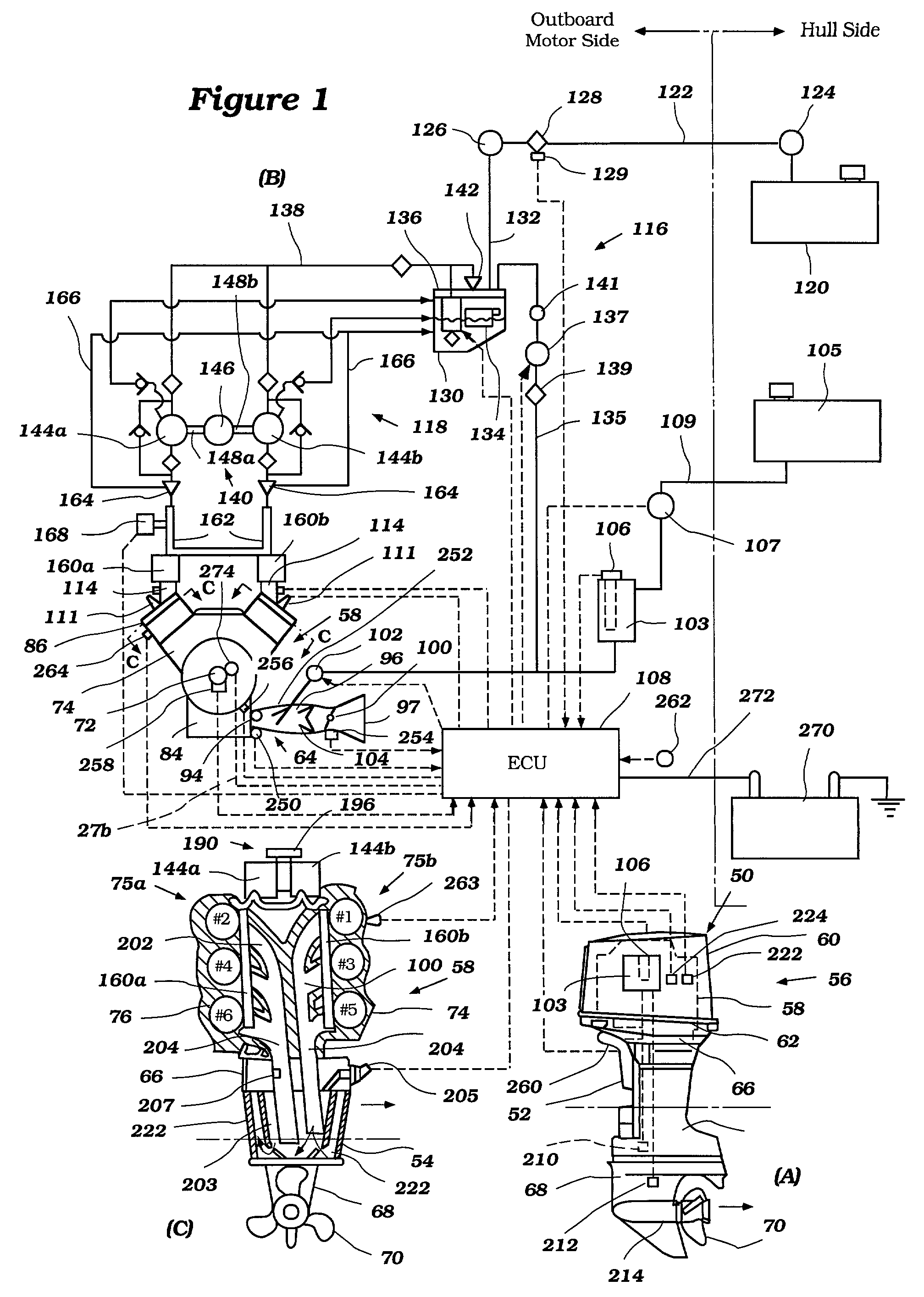
[0035] With reference now to FIG. 1, an outboard motor with an engine diagnostic system having certain features, aspects and advantages of the present invention will be described. The engine diagnostic system is described in conjunction with an outboard motor to provide an exemplary environment in which the system may be employed. Although the engine diagnostic system has particular applicability to an outboard motor, it is anticipated that the engine diagnostic system can have utility in other environments of use. In particular, the engine diagnostic system may also find utility in applications where the engine is compact, used in remote locations, or both. Such applications also might include, without limitation, engines in personal watercraft, small jet boats, motorcycles and off-road vehicles.
[0040] As is typical with outboard motor practice, the illustrated engine 58 is supported in the powerhead 56 so that a crankshaft 72 (see FIG. 1(B)) can rotate about a generally vertically extending axis. FIG. 1(B) schematically illustrates the engine from a top view. The vertical mounting of the crankshaft 72 facilitates the connection of the crankshaft 72 to a driveshaft (not shown) that depends into and through the driveshaft housing 54. The driveshaft drives the propeller 70 through a forward, neutral and reverse transmission (not shown) contained in the lower unit 68. Of course, other suitable types of transmissions also can be used with certain features, aspects and advantages of the present invention.

Problems solved by technology

However, as the number of sensors in an engine have increased, the diagnostic codes have become more complicated and difficult to understand.
Moreover, as engines have become more sophisticated and complicated, many engine technicians do not have the requisite skills to diagnose engine malfunctions.

Method used


Image

  • Diagnostic system for engine
  • Diagnostic system for engine
  • Diagnostic system for engine

Examples


Embodiment Construction

[0035] With reference now to FIG. 1, an outboard motor with an engine diagnostic system having certain features, aspects and advantages of the present invention will be described. The engine diagnostic system is described in conjunction with an outboard motor to provide an exemplary environment in which the system may be employed. Although the engine diagnostic system has particular applicability to an outboard motor, it is anticipated that the engine diagnostic system can have utility in other environments of use. In particular, the engine diagnostic system may also find utility in applications where the engine is compact, used in remote locations, or both. Such applications also might include, without limitation, engines in personal watercraft, small jet boats, motorcycles and off-road vehicles.

[0036] In the lower right hand view of FIG. 1 (i.e., FIG. 1(A)), the outboard motor is depicted in side elevation view and is identified generally by the reference numeral 50. The outboard ...


PUM


Abstract

A diagnostic system is provided to aid a technician or engineer in diagnosing an internal combustion engine. The diagnostic system comprises an electronic control unit that is operatively coupled to a data storage device and to one or more engine sensors. The electronic control unit is configured to collect data from the one or more engine sensors and to store that data in the data storage device. A computer is selectively coupled to the data storage device. The computer program is configured to display specific sets of data stored in the data storage device in various formats.

Description

PRIORITY INFORMATION[0001] The present application (i) is a continuation-in-part of U.S. patent application Ser. No. 09 / 579,908 filed May 25, 2000, which is based on and claims priority to Japanese Patent Application No. 11-146451 filed May 26, 1999 and Japanese Patent Application No. 11-304160 filed Oct. 26, 1999 and (ii) is based on and claims priority to Japanese Patent Application No. 2000-358569 filed Nov. 24, 2000, Japanese Patent Application No. 2000-358572 filed Nov. 24, 2000, Japanese Patent Application No. 2000-358573 filed Nov. 24, 2000 and Japanese Patent Application No. 2000-358570 filed Nov. 24, 2000. The entire contents of these applications are hereby expressly incorporated by reference.[0002] 1. Field of the Invention[0003] This invention relates to engine diagnostics and, in particular to an improved apparatus and method for identifying and diagnosing various engine problems.[0004] 2. Related Art[0005] Internal combustion engines are commonly used to power boats an...

Claims


Application Information

Patent Timeline
Patent Type & Authority Applications(United States)
IPC IPC(8): F02B1/00G01M15/04G06F19/00G06G7/70
CPCG01M15/04
Inventor FUJINO, KENICHIMOTOSE, HITOSHIKATO, MASAHIKONANAMI, MASAYOSHI
Owner YAMAHA MARINE KK
Learn More