Paramagnetic particle detection

a technology of magnetism and particle, applied in the direction of magnetic property measurement, electrical testing, masers, etc., can solve the problems of reducing the number of analytical steps, changing the inductance of the coil, and speeding up the time required for an assay

Inactive Publication Date: 2001-12-13
RANDOX LAB LTD
View PDF12 Cites 18 Cited by
  • Summary
  • Abstract
  • Description
  • Claims
  • Application Information

AI Technical Summary

Benefits of technology

[0016] The driver signal usually has a frequency of above 200 kHz and more particularly preferably has a frequency above 500 kHz. This is because at higher frequencies a given change in the inductance of a coil will result in a larger change in the resonant frequency of the tuned circuit. Accordingly, operating the circuit at a higher frequency increases the sensitivity of the system.
[0019] Preferably the apparatus comprises a phase locked loop oscillator circuit. This is particularly advantageous because as mentioned above, this allows the resonant frequency of the tuned circuit to be accurately determined without human intervention. This is an automatic procedure resulting in highly accurate results.
[0026] Accordingly, the present invention also provides a method of performing an assay using magnetic particles as labels. This is achieved using a substrate to which has been immobilized a layer of molecules appropriate to the assay. The reaction is designed in such a way that bonds form between the coating on the magnetic particle and the immobilized layer on the substrate. The number of particles bonding to the substrate depends on the concentration of species being measured. Accordingly, by measuring the change in the resonant frequency of the tuned circuit when the substrate is contained within, and when the substrate is not contained within the coil, allows the number of magnetic particles bound to the substrate to be determined.
[0030] It will be realised that the third aspect of the present invention can advantageously be implemented using the first and second aspects of the present invention. Accordingly, the above described electronic circuitry can be used to generate an output directly related to the number of immobilized PMP's on the strip. In this approach, the PMP particles are now being used as markers and separate fluorescent, radioactive, chemiluminescent or other markers are not required. This considerably reduces the number of analytical steps and speeds up the time required for an assay. Furthermore, the electronic circuitry is physically small enough to allow the development of a hand-held instrument.

Problems solved by technology

Because the self-inductance of a coil depends on the permeability of the material within the coil, placing a sample containing magnetic particles in a coil will result in a change in the inductance of the coil.
This considerably reduces the number of analytical steps and speeds up the time required for an assay.
Current analytical immunoassay systems using fluorescent or similar markers require expensive specialized equipment and it is not practical to make them into hand-held systems.
They are generally not suitable for use in tests where the actual concentration of a species is being determined.

Method used


Image

  • Paramagnetic particle detection
  • Paramagnetic particle detection
  • Paramagnetic particle detection

Examples


Embodiment Construction

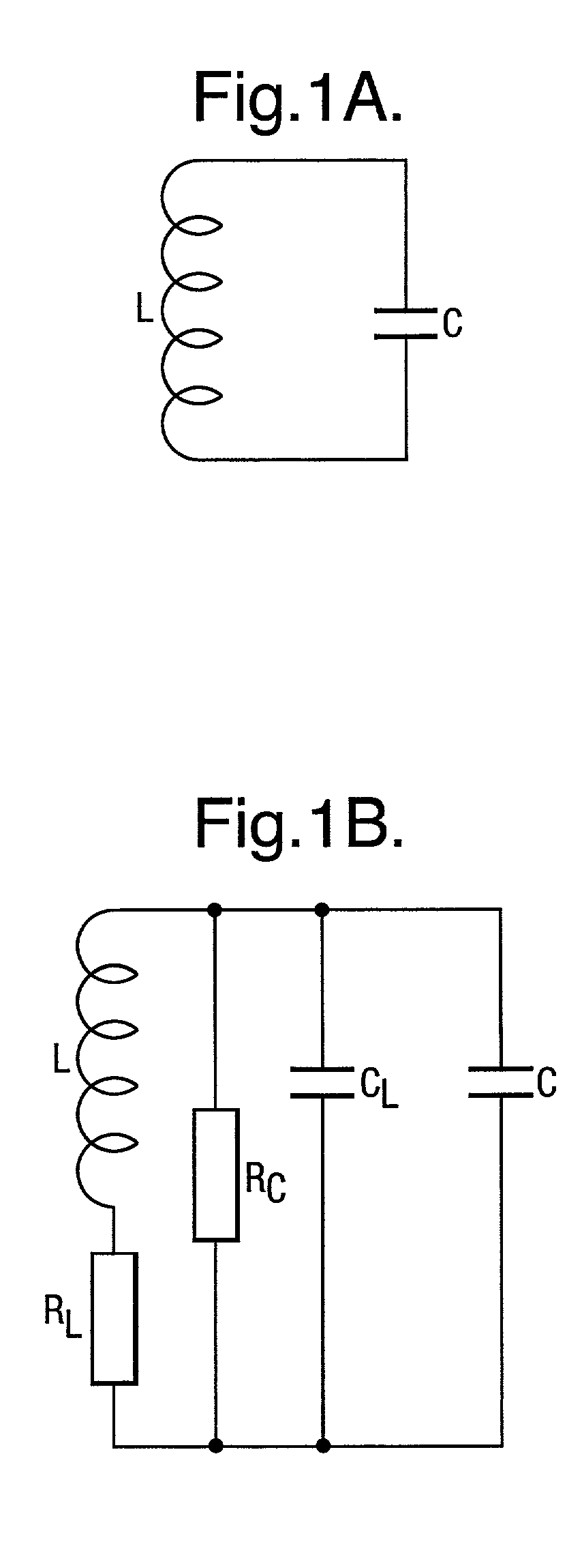
[0047] In one example of the present invention, the number of coated paramagnetic particles on a plastic strip is determined by placing the strip in a coil of insulated wire and observing the effect their presence has on the self-inductance, L, of the coil. The assumption is that the only significant contribution to changes in the inductance of the coil comes from the high magnetic permeability of the particles.

[0048] The self-inductance of a uniform helical coil with a large number of turns is given by:

L.apprxeq..mu..mu..sub.0m.sup.2lA (1)

[0049] where:

[0050] .mu..sub.0=permeability of a vacuum (4.pi..times.10.sup.-7 H m.sup.-1);

[0051] .mu.=relative permeability of the core;

[0052] m=number of turns per unit length;

[0053] l=length; and,

[0054] A=cross-sectional area of the coil.

[0055] When a plastic strip, with n paramagnetic particles attached to it, is placed in the coil, the effective value of .mu. for the coil is some value related to the individual permeabilities of the plastic i...


PUM

PropertyMeasurementUnit
frequencyaaaaaaaaaa
diameteraaaaaaaaaa
resonant frequencyaaaaaaaaaa

Abstract

A method of determining the number of magnetic particles within a sample using a tuned circuit having a capacitor and a coil. The method comprises: a. determining the difference in the resonant frequency of the tuned circuit when the sample is exposed to a magnetic field generated by the coil and when the sample is not exposed to the magnetic field generated by the coil; and b. using the difference in the resonant frequency to determine the number of magnetic particles within the sample.

Description

[0001] The present invention relates to a method and apparatus for determining the number of magnetic particles within a sample, for example a method of determining the number of magnetic particles when performing an immunoassay.[0002] The technique allows coated paramagnetic particles (PMP's) to be used as labels and to detect them using a novel electronic circuitry design.DESCRIPTION OF THE PRIOR ART[0003] The PMP's are typically 2.8 .mu.m in diameter and consist of a core of a paramagnetic material coated with a suitable polymer layer to which are attached antibody / antigen layers depending on the particular application of the PMP. Currently, the main application of these particles is in sample separation, purification and as a solid phase for immunoassays.[0004] In a typical immunoassay, the PMP's are coated with proteins allowing them to be used as the solid phase material on which an immune reaction takes place. The immune reaction is detected and quantified using a label such ...

Claims


Application Information

Patent Timeline
Patent Type & Authority Applications(United States)
IPC IPC(8): G01N27/72G01N33/543G01R33/12
CPCG01R33/1223Y10S436/804
Inventor HAWKINS, PETERLUXTON, RICHARD WILLIAM
Owner RANDOX LAB LTD
Why Eureka
Try Eureka