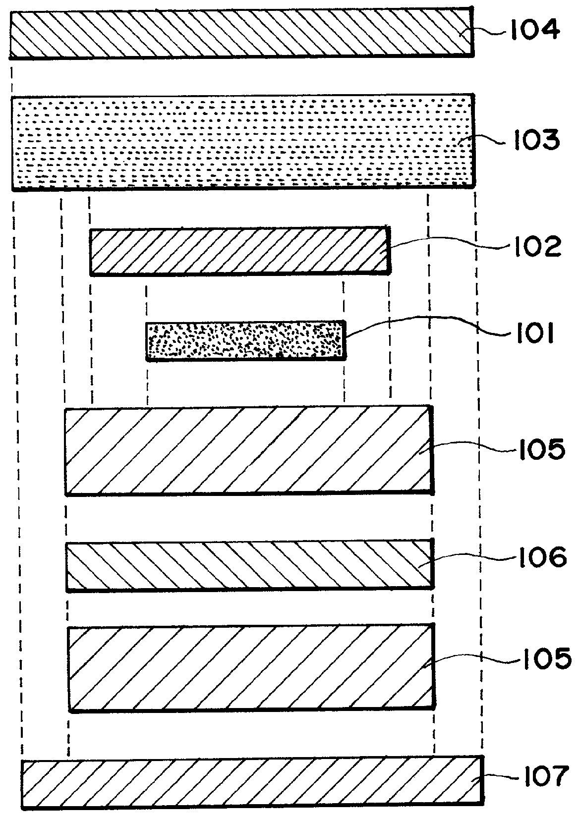
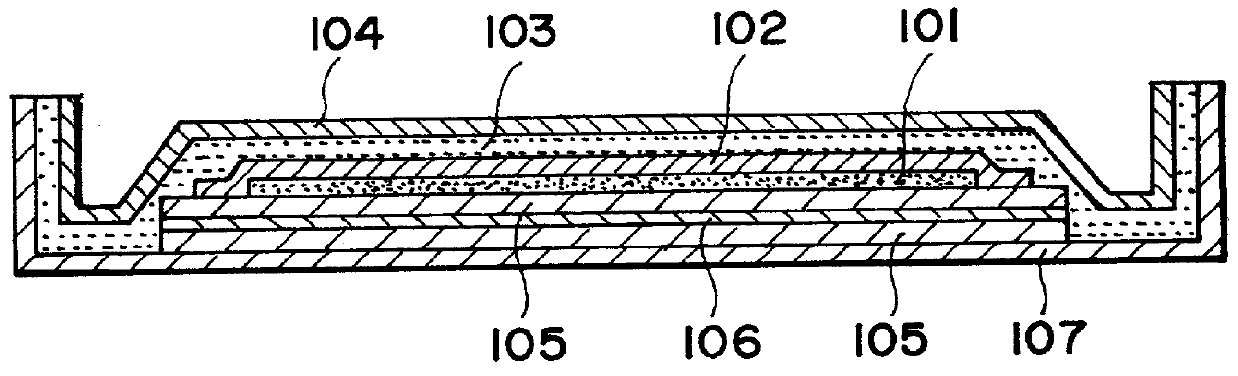
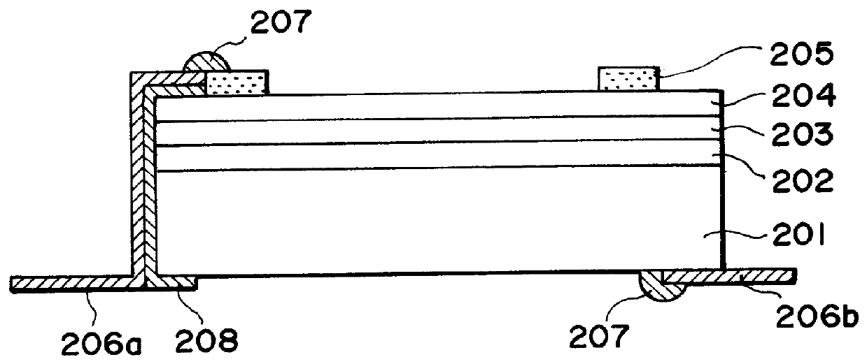
Solar cell module

a solar cell and module technology, applied in lighting and heating apparatus, ventilation systems, heating types, etc., can solve the problems of inferior appearance, peeling of laminated modules, and inferior scratch resistan

Inactive Publication Date: 2001-12-27
CANON KK
View PDF0 Cites 47 Cited by
  • Summary
  • Abstract
  • Description
  • Claims
  • Application Information

AI Technical Summary

Problems solved by technology

Such a solar cell module having a fluorine-containing polymer as a light-incidence side surfacemost coating material has an inferior scratch resistance than a solar cell module comprising a glass substrate as a light-incidence side surface material.
However, in case where the inorganic fibrous sheet such as glass fiber is exposed to an edge of the solar cell module, external moisture is liable to intrude to lower the electrical insulation or cause a peeling of the laminated module and provide an inferior appearance.
However, the insulating film is disposed to protrude out of the module substrate, and no consideration has been paid to bending of the module substrate.
In a conventional solar cell module having such a structure, a lowering in electrical insulation is inevitably caused when used outdoors for a long period even if the end portion of the glass fiber is prevented from being exposed at the edge of the module and a silane coupling agent is applied to the glass fi

Method used


Image

  • Solar cell module
  • Solar cell module
  • Solar cell module

Examples


example 2

[0113] A solar cell module was prepared in the same manner as in Example 1 except that the back-side integrated laminate film was replaced by a laminate of EVA / PET / EVA (of 230 .mu.m / 100 .mu.m / 230 .mu.m), wherein EVA was a filler resin sheet same as in the filler resin sheet 403 disposed on the light-receiving side in the module of Example 1 and PET was the same as in Example 1, except for their thicknesses.

example 3

[0114] The solar cell module was prepared in the same manner as in Example 1 except for the following modifications.

[0115] The sizes of the respective member were changed as follows. The inorganic fibrous sheet 402 was larger by 15 mm for each side, the back-side integrated laminate film 405 was larger by 45 mm for each side, the substrate 406 was larger by 80 mm for each side, and the filler resin sheet 403 and the transparent film 404 were both larger by 90 mm for each side, respectively compared with the cell block 401.

example 4

[0116] The solar cell module was prepared in the same manner as in Example 1 except for the following modifications.

[0117] A cell block in layer outer sizes of 300 mm .times.2400 mm was prepared by increasing the number of solar cells connected in series. As the increase in cell block size made difficult the evacuation from the inside of the module, a 100 .mu.m-thick inorganic fibrous sheet (basis weight=20 g / m.sup.2, binder acrylic resin content=4.0%, glass fiber diameter=10 .mu.m) in a size larger by the cell block by 5 mm for each side was inserted between the cell block and the back-side integrated laminate film.


PUM


Abstract

A solar cell module includes a substrate, a photo-electricity generating device (i.e., a solar cell or a block of solar cells), a filler resin sealing the photo-electricity generating device on the substrate, and a surface film covering the filler resin. An insulating film is inserted between the photo-electricity generating device and the substrate so as to be inside the substrate, and an inorganic fibrous sheet is inserted between the photo-electricity generating device and the surface film so as to be disposed inside the insulating film. The substrate is bent at a portion thereof free from the insulating film. The solar cell member thus provided can exhibit a long-term reliability for outdoor use because of effective suppression of intrusion of moisture thereinto.

Description

FIELD OF THE INVENTION AND RELATED ART[0001] The present invention relates to a solar cell module including a photo-electricity generating device (i.e., a solar cell or a block of solar cells) fixed with a resin onto a substrate and covered with a surface film. More specifically, the present invention relates to a solar cell module having an excellent inflammability and an excellent moisture resistance and also a bent structure suitable for assembly.[0002] Hitherto, a type of solar cell module including a photo-electricity generating device fixed onto a substrate with a resin and covered with a surface film has been known. As the resin, EVA (ethylene-vinyl acetate copolymer) has been widely used. As the surface film, it has been known to use a film of a fluorine-containing resin, such as tetrafluoroethylene-ethylene copolymer or polyvinyl fluoride, or a transparent fluorine-containing polymer film formed by coating with a fluorine-containing resin paint.[0003] Such a solar cell modu...

Claims


Application Information

Patent Timeline
IPC IPC(8): F24D5/00H01L31/042H01L31/04H01L31/048
CPCB32B17/04E04D3/366E04D2001/3447F24D5/005H02S20/23Y02B10/12Y02B10/14Y02E10/50Y10S454/90H01L31/048Y02B10/10E04D1/2928
Inventor KOMORI, AYAKOMORI, TAKAHIROKATAOKA, ICHIROYAMADA, SATORUSHIOTSUKA, HIDENORI
Owner CANON KK
Why Eureka
Try Eureka