Device for maintaining separate ingredients in liquid food products

a technology for liquid food products and ingredients, applied in the field of liquid food product storage, can solve the problems of not being used with currently sold beverages and liquid mixtures, flavors, oils, vitamins, supplements, etc., and achieve the effects of convenient use, safe storage, and selective dispensing into the container

Inactive Publication Date: 2002-01-31
CASTILLO JAMES A
View PDF0 Cites 12 Cited by
  • Summary
  • Abstract
  • Description
  • Claims
  • Application Information

AI Technical Summary

Benefits of technology

[0009] The present invention seeks to overcome the disadvantages and shortcomings of the prior devices by providing improved structures for holding ingredients separately within a container which is inexpensive to manufacture, convenient and easy to use, and prevents accidental unsealing or release during shipping or handling.
[0018] In a seventh embodiment, the device comprises a sub-container body in cylindrical form, removably mounted in a neck of the container and covered by the container cap, having a proximate end with inclined walls leading to a central opening and an annular flange adjacent the inclined walls, such that when the sub-container body is removed from the container neck, the proximate end can be inserted into the neck opening until the annular flange abuts the neck rim, whereby ingredients contained in the sub-container body can be dispensed into the container without risk of spilling or splashing outside the container. The sub-container body may be mounted to the underside of the container cap, or held by its annular flange between the cap and the rim of the container neck. The inclined walls and annular flange serve to guide the proximate end positively into the neck opening and be held securely in place.
[0019] In an eighth embodiment, the device comprises a sub-container body in cylindrical form, removably mounted in the container neck and covered by the container cap, having a proximate end with inclined walls leading to a central opening, an annular flange adjacent the inclined walls, and an inner wall parallel to its cylindrical axis dividing the interior of the sub-container body into a plurality of axially oriented compartments, wherein each compartment is formed with a dispensing orifice at the proximate end of the sub-container body, each orifice being separately sealed, such that when the sub-container body is removed from the container neck and one or more of the compartment orifices is selectively unsealed, the proximate end can be inserted into an opening in the container neck with the annular flange abutting an upper rim of the neck, whereby ingredients contained in the selected compartments can be dispensed into the container without risk of spilling or splashing outside the container.
[0020] In a ninth embodiment, the device comprises a sub-container body in cylindrical form which is removably mounted in the container neck and covered by the container cap, having a proximate end provided with an annular flange fixed to its outer surface and screw threads formed on the outer surface of the proximate end on an upper side of the annular flange, the container neck having complementary inner threads on an inner surface recessed in the neck opening, such that when the sub-container body is removed from the container neck, the proximate end of the sub-container body can be inserted in and threaded to the inner surface of the container neck until its annular flange abuts the rim of the neck, whereby ingredients in the sub-container body can be dispensed by shaking or mixing with fluid in the container without risk of spilling or splashing outside the container. The outer threading of the sub-container body and inner threading of the container neck and the annular flange allow the parts to be securely held together. Sealing films may be provided on upper and lower sides of the annular flange.
[0021] In a tenth embodiment, the device comprises a sub-container body in cylindrical form which is removably mounted in the container neck and covered by the container cap, said sub-container body having a proximate end with an annular flange fixed to its outer surface and screw threads formed on the outer surface of the proximate end on an upper side of the annular flange, the container neck having complementary inner threads on an inner surface recessed in the neck opening, the sub-container body having an inner wall parallel to its cylindrical axis dividing the interior of the sub-container body into a plurality of axially oriented compartments, wherein each compartment is formed with a dispensing orifice at the proximate end of the sub-container body, each orifice being separately sealed such that when the sub-container body is removed from the container neck, one or more of the compartment orifices can be selectively unsealed, and the proximate end of the sub-container body can be inserted into and threaded to the inner surface of the container neck until the annular flange abuts with the neck rim, whereby ingredients in the unsealed compartments can be dispensed by shaking or mixing with fluid in the container without risk of spilling or splashing outside the container. The plurality of compartments and separately sealed orifices allow different ingredients to be selectively dispensed in the container. Sealing films may be provided on upper and lower surfaces of the annular flange.
[0024] With these improved devices, multiple ingredients can be safely stored separately from the carrier liquid and conveniently used and selectively dispensed into the container according to the user's tastes. Thus, a wide range of new liquid food products can be provided with better flavor, longer shelf life, and using otherwise unstable ingredients, and without any or with reduced amounts of preservatives.

Problems solved by technology

Some flavorings, oils, vitamins, supplements, medicines, and other ingredients when mixed with water, soda, or other liquid media are unstable, and therefore may not be used with currently sold beverages and liquid mixtures.
Oxygenated water is known to have health benefits but is chemically reactive, and therefore flavors, vitamins, supplements, and pharmaceuticals cannot be combined with it in a stored product.
However, these devices may be unsafe or messy to use since a high applied pressure must be used to burst open the compartment, and may cause the ingredients spew out of the container or back toward the user.
However, these devices are not suitable for the current vending machine environment, since the outer sealing member can become accidentally dislodged or punctured during transport or handling.
These types of devices have the disadvantage that the ingredients are completely discharged into the liquid upon release, and cannot be metered or controllably added to the liquid according to the tastes of the user.
However, this type of device has only a single compartment and does not have provision for easily metering ingredients into the container after the seal is opened.
However, the sub-compartments in these devices are disposed at opposite ends of the sub-container element and are opened by threaded elements, thereby making them costly to fabricate and awkward to use.

Method used


Image

  • Device for maintaining separate ingredients in liquid food products
  • Device for maintaining separate ingredients in liquid food products
  • Device for maintaining separate ingredients in liquid food products

Examples


first embodiment

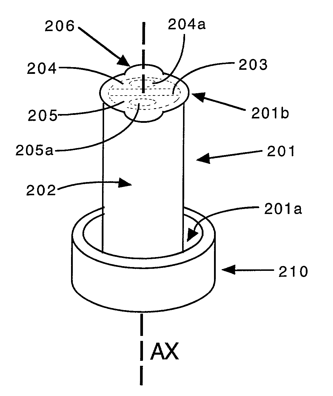
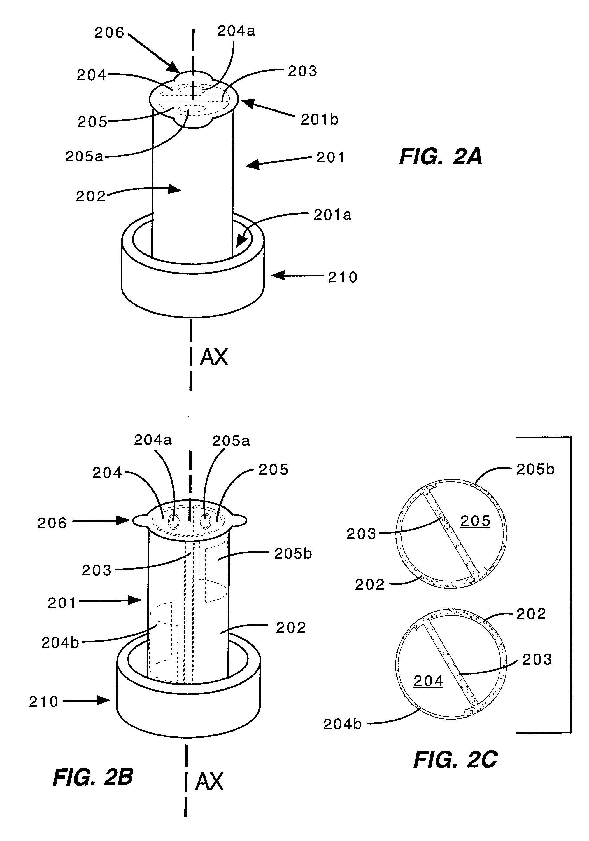
[0042] Referring to FIGS. 2A and 2B, the device for use with a bottle container has a sub-container body 201 in cylindrical form with a proximate end 201a mounted to the underside of the container cap 210. The sub-container body 201 has squeezable plastic outer walls 202 and at least one inner divider wall 203 which is aligned in parallel with a cylinder axis AX of the sub-container body. The divider wall 203 divides the interior of the sub-container body into two axially oriented compartments 204, 205. A greater number of compartments can be formed by using more than one divider wall.

[0043] The compartments 204, 205 are used to contain respective flavorings, oils, vitamins, supplements, medicines, and other ingredients to be mixed in the carrier liquid at the time of use. The compartments have respective dispensing orifices 204a and 205a formed through closure walls at the distal end 201b of the sub-container body. The orifices of the individual compartments are sealed with individ...

second embodiment

[0047] In FIGS. 3A, 3B, and 3C, the device is shown having a cylindrical sub-container body 301 with its proximate end detachably mounted to the underside of the container cap 310 by detent surfaces 307 snap-fitted onto projections 311 on the underside of the cap. The sub-container body 301 has squeezable plastic outer walls 302. The divider wall 303 divides the interior of the sub-container body 301 into compartments 304 and 305. The compartments 304 and 305 have respective dispensing orifices 304a and 305a formed at the proximate end of the sub-container body. As shown in more detail in FIGS. 3D and 3E, the orifices are sealed with removable sealing tabs 304c and 305c, and have anti-drip edges 312. In this embodiment, positioning the compartment orifices at the proximate end keeps them away from the carrier liquid and reduces the possibility of seepage or liquid penetration into the seals.

[0048] In FIGS. 4A, 4B, and 4C, a third embodiment of the device, similar to the first embodi...

fourth embodiment

[0050] In FIGS. 5A, 5B, and 5C, the device is shown having a sub-container body 501 in cylindrical form with its proximate end 501a mounted to the underside of the container cap 510. The sub-container body is formed with squeezable plastic outer walls 502, and has divider walls 503 aligned transverse to the cylinder axis AX dividing the interior of the sub-container body into a plurality of transversely oriented compartments 504, 505, and 506. The compartments have respective orifices 504a, 505a, and 506a formed at predetermined positions of the outer walls for each compartment.

[0051] In FIG. 5D, the sub-container body 501 is shown in greater detail having an indented detent surfaces 507 to which projections 511 on the underside of the cap are snap-fitted to mount the sub-container body to the cap. The portions of the outer walls at the positions of the orifices can be formed with puckers 504d, 505d, and 506d for better directing of ingredients from the orifices under pressure. In F...


PUM

PropertyMeasurementUnit
thicknessaaaaaaaaaa
thicknessaaaaaaaaaa
diameteraaaaaaaaaa

Abstract

A device for maintaining ingredients separately within a container, of the type having a removable container cap applied on a neck with a central opening, has a sub-container body mounted in the container neck which is formed with a proximate end having screw threads which can be engaged with internal screw threads in the container neck for holding them securely together to allow the ingredients to be shaken out of the sub-container body and mixed with fluid in the container. The sub-container body can have inner divider walls forming multiple compartments with respective orifices for dispensing ingredients selectively from the compartments. The sub-container body may be sealed to the underside of the cap with a sealing film, or seated on the neck rim and held by the cap. In one version, the proximate end of the sub-container body has a protruding shape with inclined walls for guiding it into the neck opening. In other versions, the sub-container body is formed integrally with the container cap, or is formed as an annular ring shape carried between inner and outer flanges of the cap. These improved devices allow viscous or powdered ingredients to be mixed by shaking with fluid in the container without risk of spilling or splashing outside the container.

Description

SPECIFICATION[0001] This application is a continuation-in-part of U.S. patent application Ser. No. 09 / 321,676, of the same title, by the same inventor, filed on May 28, 1999.[0002] This invention generally relates to a device for maintaining ingredients separate in liquid food products until the time of use, and more particularly, to such improvements as used with standard beverage bottles or cans.BACKGROUND OF INVENTION[0003] In the storage of liquid foodstuffs, and particularly beverages, the food product can have better flavor, have a longer shelf life, be made without preservatives, and / or can use less stable or unstable ingredients if certain of the ingredients can be stored separately from the carrier liquid until the food product is to be consumed. For example, a beverage can have better taste if the flavoring can be stored in dry form and mixed with the carrier liquid just prior to use. Some flavorings, oils, vitamins, supplements, medicines, and other ingredients when mixed...

Claims


Application Information

Patent Timeline
Patent Type & Authority Applications(United States)
IPC IPC(8): B65D81/32B65D51/28
CPCB65D51/28Y10S215/08
Inventor CASTILLO, JAMES A.
Owner CASTILLO JAMES A
Why Eureka
Try Eureka