Bioremediation of nitrate contaminated groundwater

a technology of bioremediation and groundwater, which is applied in the direction of biological water/sewage treatment, filtration separation, and separation processes, etc., can solve the problems of inability to provide additional airflow

Inactive Publication Date: 2002-02-21
NAT RES COUNCIL OF CANADA
View PDF0 Cites 8 Cited by
  • Summary
  • Abstract
  • Description
  • Claims
  • Application Information

AI Technical Summary

Problems solved by technology

It will be appreciated that the complexity and cost of a system including such a large number of wells would be prohibitive.
Certain conditions (high dissolved oxygen concentration and low content of dissolved organic compounds) combined with a nitrate source run-off may result in nitrate accumulation in groundwater.
However, no additional influx of air is provided.
It is important to note that underdosage of ethanol results in incomplete denitrification, while overdosage may lead to a formation of hydrogen sulfide (H.sub.2S), if groundwater contains a significant amount of sulphates.

Method used


Image

  • Bioremediation of nitrate contaminated groundwater
  • Bioremediation of nitrate contaminated groundwater
  • Bioremediation of nitrate contaminated groundwater

Examples


Embodiment Construction

[0046] Extensive biochemical characterization revealed the presence of elevated concentrations of nitrate in groundwater at Bagotville Air Force Base, Quebec, Canada. Field study suggested no evidence of denitrification due to the absence of a carbon source. This finding was confirmed by simulations of nitrate transport and biodegradation using RT3D model. Consequently, the remediation sequence described above was carried out in order to decrease the level of nitrates in ground water.
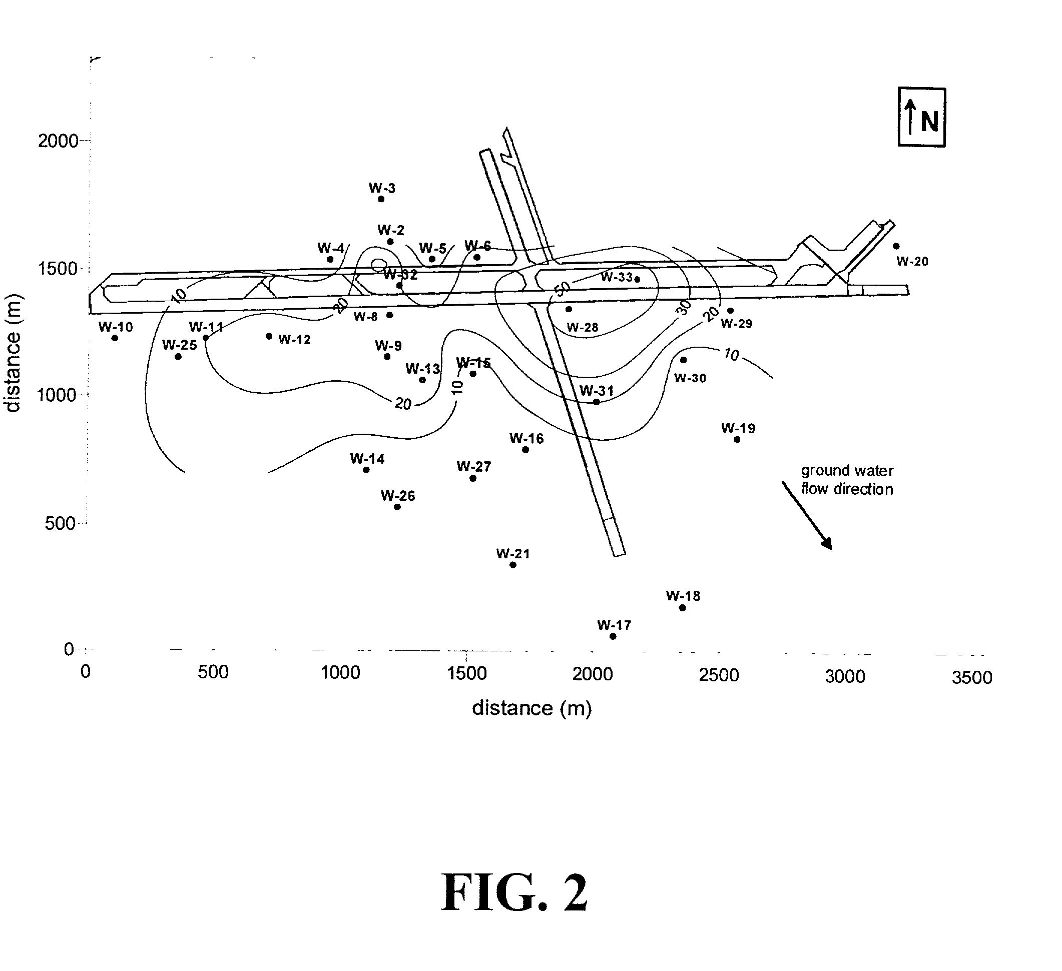
Site Hydrogeology

[0047] The soil at the site consists mostly of sand (from fine to coarse) with a small amount of clay and silt. This composition provides good permeability. The sand is located above the impermeable bed of clay which constitutes the lower limit of the aquifer. The base of the aquifer varies from 10-20 m to the north of the runways to 50-70 m south of the runways.

[0048] Groundwater is present all over the site. Rivers Mars and Gauthier constitute natural limits (sinks) of the aquifer. Th...


PUM

PropertyMeasurementUnit
concentrationaaaaaaaaaa

Abstract

The invention disclosed relates to a method and apparatus for the denitrification of groundwater in situ in an aquifer under substantially anaerobic conditions, the method comprising (a) providing a network, including an extraction well for removal of groundwater from the aquifer and a plurality of injection wells for returning groundwater to the aquifer, the injection wells being arranged in a line substantially perpendicular to the direction of groundwater flow, the extraction well being located downstream or upstream of the line of injection wells, and the spacing of the wells and the number of injection wells being determined by the mathematical relationship <math-cwu id="MATH-US-00001"> <number>1</number> J = C p + nC 1 W min ( 1 ) <mathematica-file id="MATHEMATICA-00001" file="US20020020664A1-20020221-M00001.NB"/> <image id="EMI-M00001" wi="216.027" he="18.00225" file="US20020020664A1-20020221-M00001.TIF" imf="TIFF" ti="MF"/> </math-cwu> where J is the cost of treatment, Cp and C1 are the costs of extraction and injection wells, respectively; n is the number of injection wells, and W is the distance across the protected area, and wherein the water stream is evenly distributed between injection wells, according to the relationship: <paragraph lvl="0"><in-line-formula>Fl=Fe/n=const (2) </in-line-formula>where F is the water flow rate (e-extraction well, i-injection well) and n is the number of injection wells, (b) removing groundwater from the aquifer by the extraction well, (c) adding a carbon source to the groundwater in a controlled manner, (d) returning the carbon source amended groundwater to the aquifer by the injection wells in even distribution, the water flow rate being controlled, and (e) monitoring the nitrate concentration of the groundwater removed from the extraction well, a decrease in nitrate concentration being indicative of denitrification.

Description

[0001] This invention relates to the remediation of nitrate contaminated aquifers, such as in agricultural areas or at airports, and in particular to a method and apparatus for providing such remediation in situ.[0002] Concern about elevated concentrations of nitrate in drinking water is growing, especially in rural areas where farming activities as well as the use of nitrate-rich fertilizers increase levels of nitrate in groundwater. Another source of nitrate in groundwater, stems from the use of urea on airport runways as a deicing agent. In this later case, urea percolation in the upper layer of soil is followed by biologically assisted hydrolysis of urea into ammonium. The aerobic nitrifying bacteria (ammonium- and nitrite-consumers) complete the transformation into nitrate. In both cases nitrates are carried with water seeping into the deeper aquifer, where they may accumulate in an aerobic environment which lacks a carbon source.DESCRIPTION OF THE PRIOR ART[0003] One prior art...

Claims


Application Information

Patent Timeline
Patent Type & Authority Applications(United States)
IPC IPC(8): B09C1/00C02F3/28
CPCB09C1/002C02F3/28C02F2101/163C02F2103/06C02F2209/00
Inventor TARTAKOVSKY, BORISGUIOT, SERGEBRETON, JEROMEDELISLE, SERGE
Owner NAT RES COUNCIL OF CANADA
Why Eureka
Try Eureka