Modern concrete paving practices impose more severe constraints on concrete quality every year.
The cost of the concrete makes up the majority of the cost of the road or airport pavement being built.
Because of the large quantity of concrete that can be produced by the contractor in a day, the contractor faces great financial risk if many days pass before he realizes the concrete he is producing is testing outside of specification mean.
This results in the contractors cost to place the concrete increasing because his fixed paving costs per hour are divided by fewer yards of concrete.
Modern concrete paving practices also call for the use of slipform pavers, which in operation consume relatively large amounts of concrete.
If the
time limit is exceeded, the concrete that is hauled will start to set before the paver places it and the paver placed concrete will not meet the required contract standards.
Secondly, and given the high quality constraints placed on the paved and / or placed concrete product, so-called
continuous mixing concrete plants have proven inadequate.
The exacting standards of thorough mixing covered by precise constituent proportion make the
continuous flow adjustment of such plants hazardous from the
quality control standpoint.
As a result, such
continuous mixing concrete plants have not been accepted in modern paving practice, at least in the North American paving market.
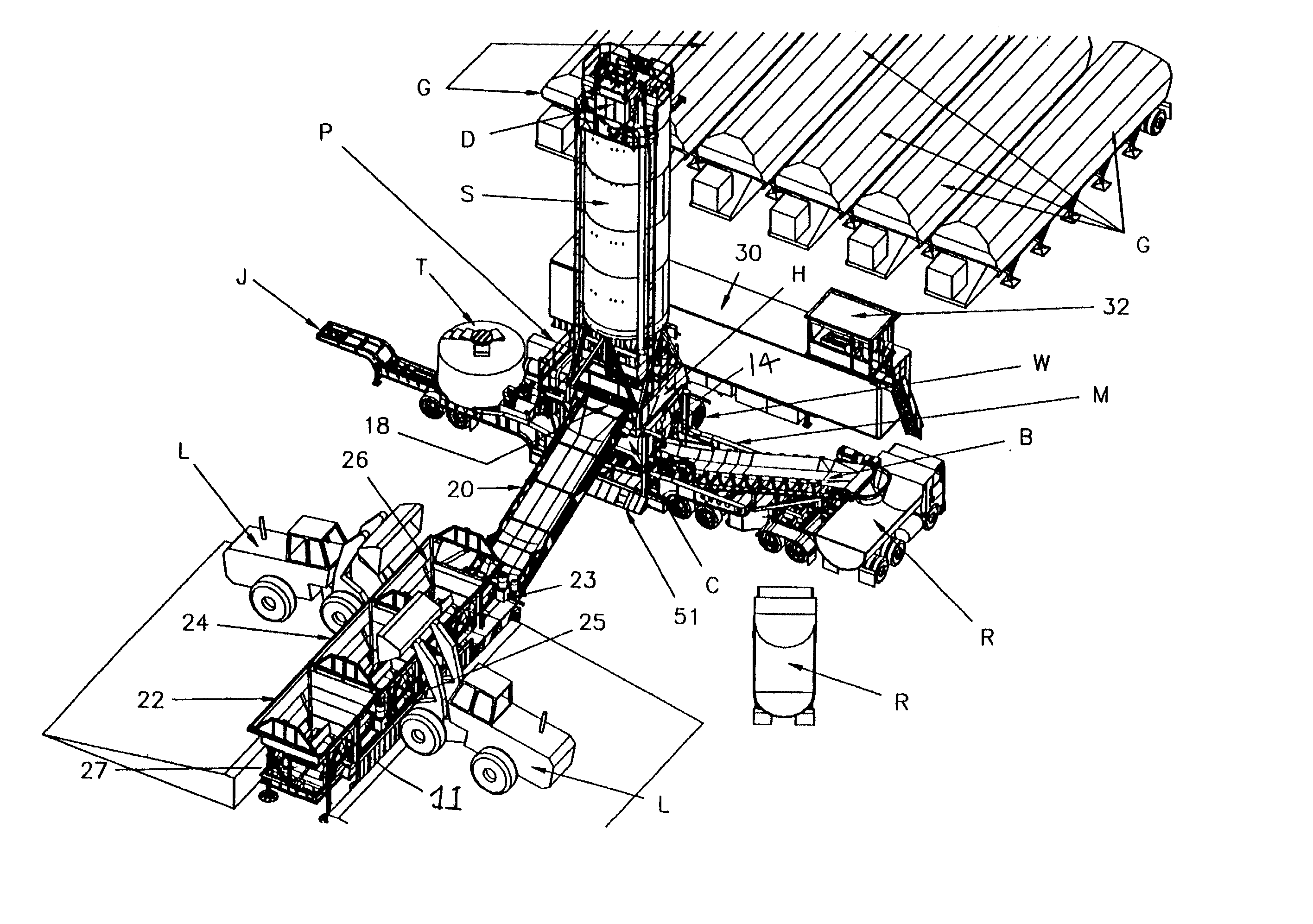
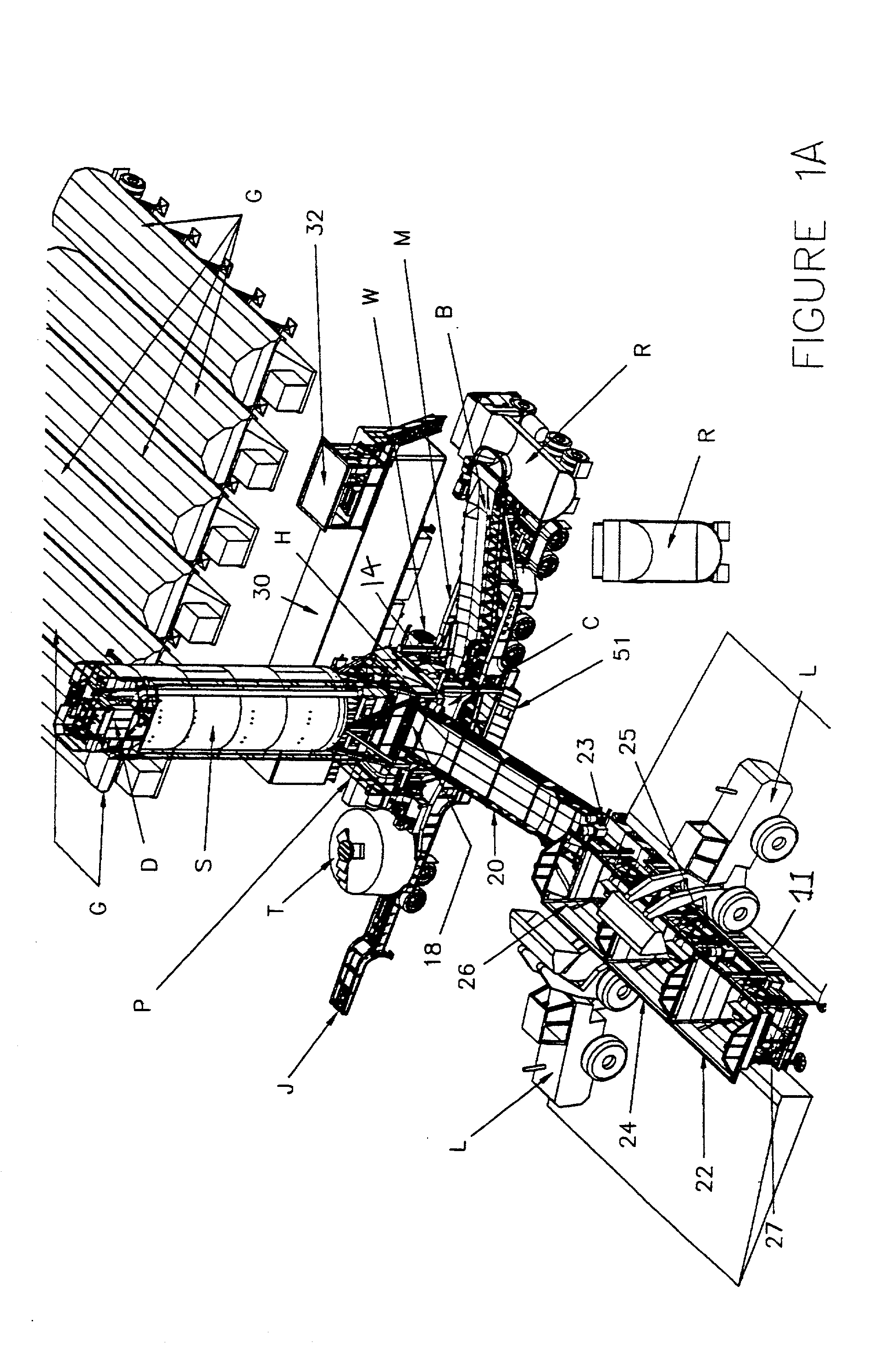
Prior art portable modern batching and mixing concrete plants are large, require concrete foundations and are difficult to erect, often consuming three to five days in
assembly.
First the feeding belt is usually gravity fed from overlying storage bins and weighing / batching hoppers. Thus, considerable weight must be supported at substantial heights from the ground on such portable plants. Using weighing belts instead of weighing hoppers is novel in the U.S. for mixing concrete. It is quite common in the
asphalt mixing
plant industry. In order to load the overlying storage bins that cannot be reached directly by a front-end
loader, separate charging conveyors with charging bins are used for each aggregate and sand. The charging bins are at an elevation that can be reached by a front-end
loader. Because of the requirement of these charging conveyors and bins, the plant site required is quite large limiting the number of places the plant may be set up.
Second, such rotating mixing drums must be tilted, and in a few cases, reversed in rotation for
discharge. This tilting of the drum superimposes a moment requirement upon the weight support requirement of the
rotating drum. As a result of the weight and moment requirements, most so-called portable concrete batching and mixing plants require concrete foundations. Further, in a few cases, reversing the mixing drum rotation not only interrupts mixing, but also consumes
momentum, and utilizes heavy reversible drives.
Third, because the rotating mixer drums are supported high in the air, if the more desirable
gravity feed of
cement is used with the rotating mixer drum, the
cement silo must be elevated even higher in the air. The resulting silo and structure requires concrete foundations. To save height, and in lieu of
gravity feed from the silo to the cement batcher, many manufacturers of conventional concrete plants use cement screws or air slides to convey the cement into the mixer. Most contractors agree these cement-conveying schemes are undesirable although many times tolerated to minimize the silo height. The principle
disadvantage of such schemes is that
aeration of the cement impedes accurate
fast measurement of the concrete.
Fourth, because tilting drum mixers are open in front for
discharge and open in the back for loading the concrete constituents into the mixer, it is very difficult to suppress the dust that results from the ingredient loading operation. The inability to adequately suppress the dust
coming out of the mixers limits the use of the plant in many urban settings.
Fifth, because the tilting /
rotating drum mixer rotates on rollers, can be driven by chain drives or gearbox driving gear on drum. The mixer drum is essentially open during the mixing process. As a result, these conventional mixers are very noisy which limits the use of this plant in many urban settings because of the high
decibel readings produced.
Generally, the larger the
plant production capacity per hour the more cumbersome and costly the plant is to transport, set-up and tear down.
This requirement further makes these plant even more cumbersome and costly to transport, set-up, tear down and maintain.
Finally, rotating / tilting drum mixers are relatively slow in delivering desired amounts of thoroughly and uniformly mixed low
slump concrete, base courses and
soil cement.
The limitation of this design is that dry material bridges in the mixer and does not discharge out of the drum readily.
Moreover, when cement substitutes are used such as slags, the concrete tends to be sticky which again impedes rapid discharge.
With low
slump or difficult mix designs, rotating / tilting drum mixers produce less than thorough mixing with
resultant "ribbons" of less than homogeneously mixed concrete when compared to a compulsory mixer.
As a result, considerable additional mixing time or "dwell time" of the concrete in the rotating / tilting drum mixer is required resulting in fewer loads of concrete being produced in an hour.
Furthermore, the production rates required in Europe are much lower because of philosophy and logistical requirements thus the size of these compulsory mixers is much smaller.
As a consequence, such compulsory mixers have not been adapted to high volume portable concrete batching and mixing plants used in North America.
Second, current "portable" concrete batching and mixing plants of the same or similar capacity require between three and five days for an equivalent move with 300 to 400 man hours being devoted to each set-up and tear down.
Thus the decision is frequently made to leave an erected plant idle and in place for paving the opposite side of a highway because it is too costly to move the plant.
Maximally, transported loads over high quality highways are normally limited to trailer vehicles having less than 85 feet length overall, 13 feet 6 inches in height (many states today allow 14'), and under 12 feet in width.
Specifically, sites for portable concrete plants can be limited.

