
Differential numerical aperture methods and device

a numerical aperture and differential technology, applied in the field of meteorology, can solve the problems of not disclosing the differential aperture to integrate a wider range of incident angles, and not disclosing the varying apertur

Inactive Publication Date: 2002-04-04
ONTO INNOVATION INC
View PDF29 Cites 50 Cited by
  • Summary
  • Abstract
  • Description
  • Claims
  • Application Information

AI Technical Summary

Benefits of technology

[0026] A primary advantage of the present invention is that it provides a device for scatterometry or ellipsometry with a minimum of moving parts, and occupying a very small footprint.
[0027] Another advantage of the present invention is that it provides a device for CD determination that may be incorporated as a module or component in an integrated semiconductor processing and manufacturing device.
[0029] Yet another advantage of the present invention is that it provides a method for scanning through a variety of incident or reflective angles, or both, by varying the numerical aperture in variable numerical aperture components.

Problems solved by technology

However, this patent does not disclose opening the aperture differentially to integrate a wider range of incident angles.
This provides a variable aperture, but does not disclose varying the aperture during a measurement cycle, and further involves separate simultaneous detection of a plurality of different angles of incident light.

Method used


Image

  • Differential numerical aperture methods and device
  • Differential numerical aperture methods and device
  • Differential numerical aperture methods and device

Examples


Embodiment Construction

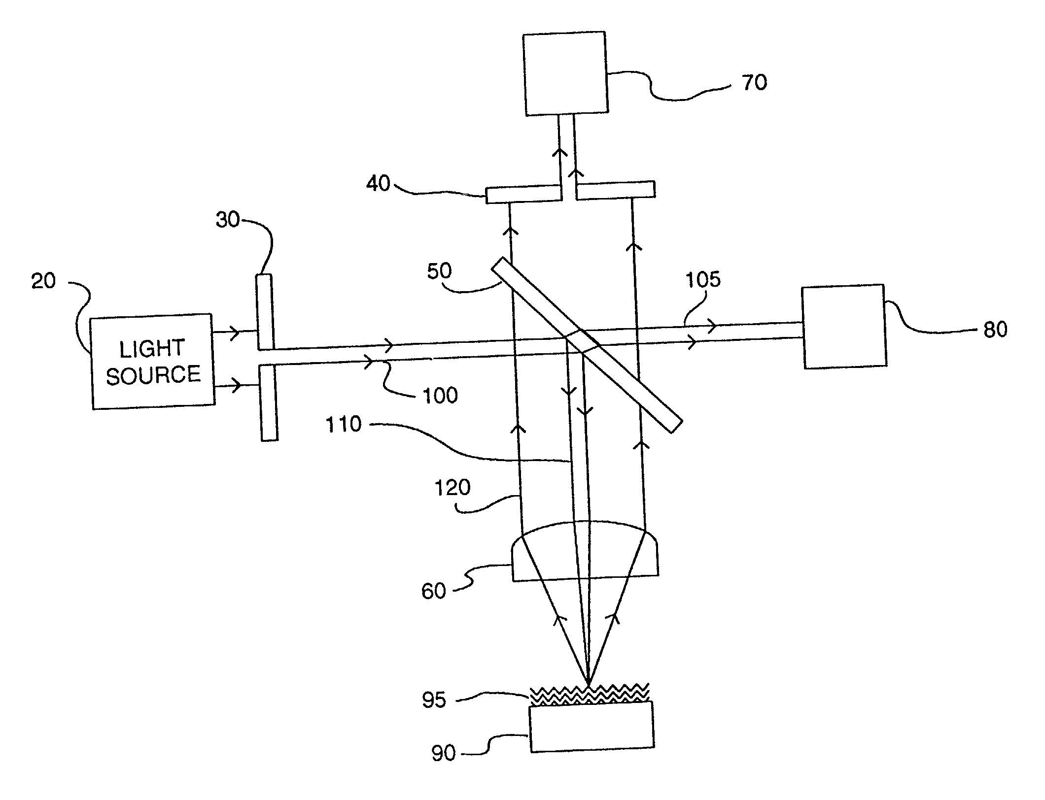
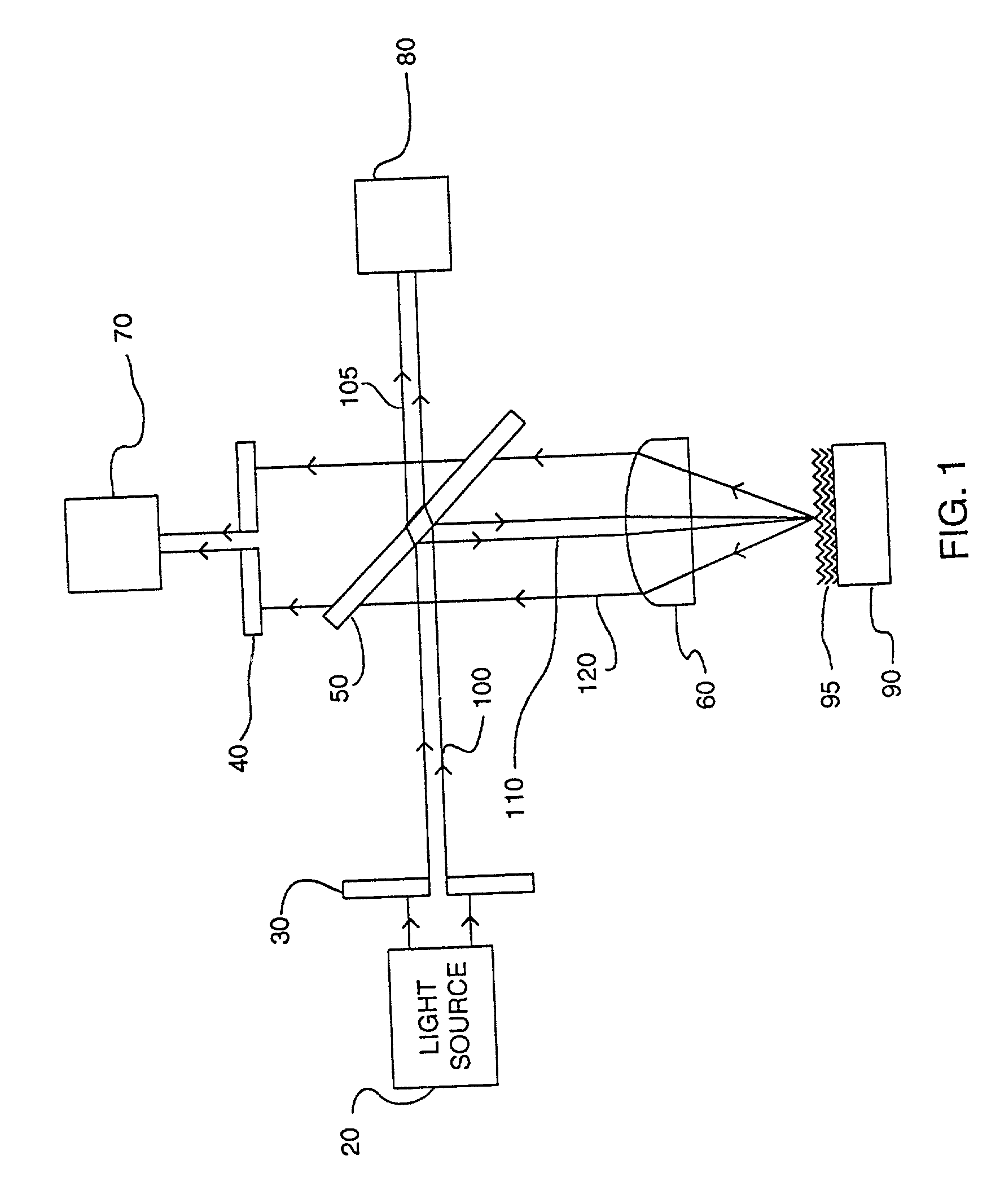
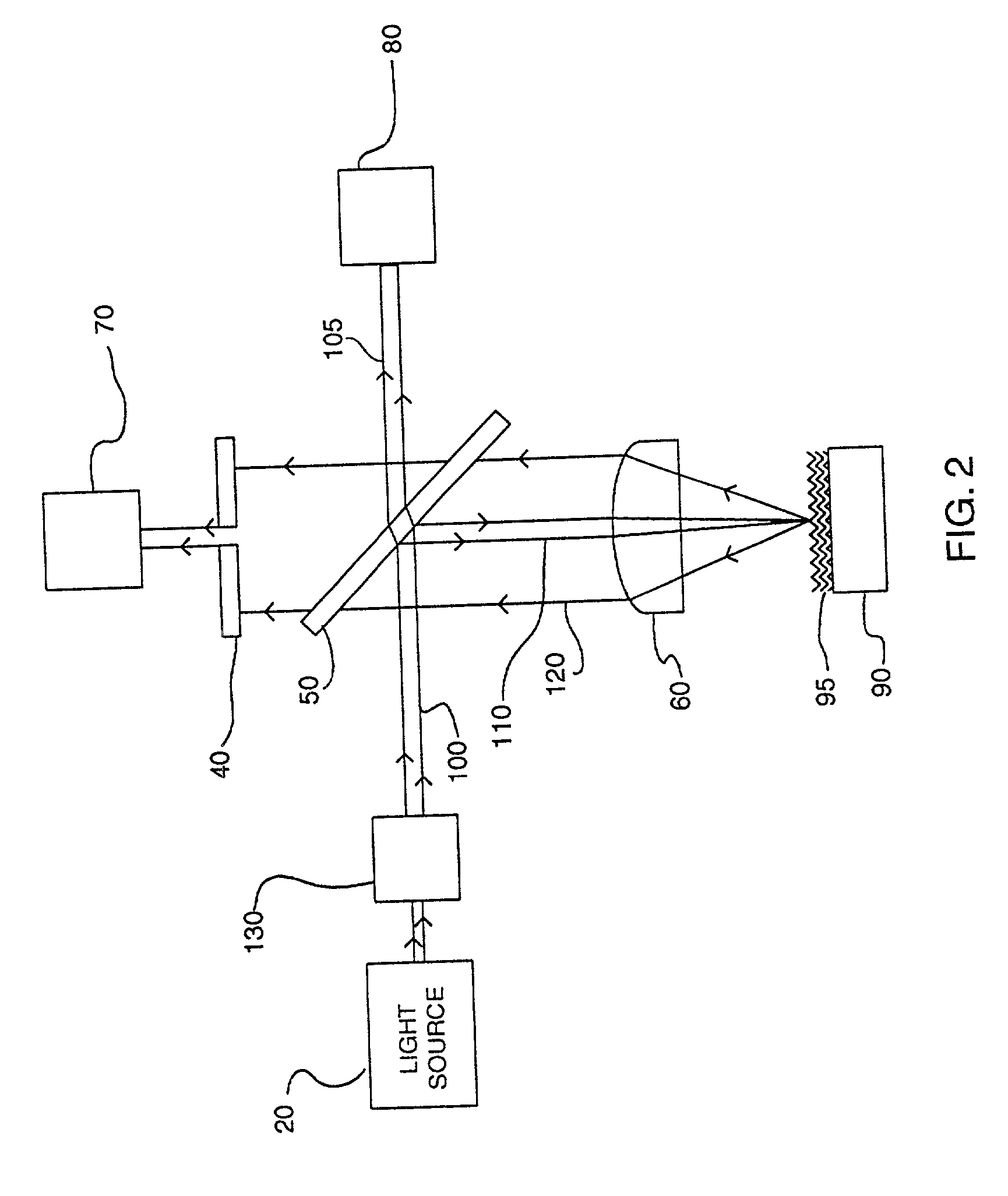
[0042] A generalized embodiment of a device of the invention is provided in FIG. 1. Light source 20 provides a source of light for illuminating beam 100, which light source 20 may produce any form of light, either within or without the visible spectrum. Light source 20 conventionally produces monochromatic light, and preferably coherent light, and thus conventional lasers, light-emitting diodes and the like may be employed. However, in embodiments of the invention, as hereafter described, other light sources and forms of light may be employed. The column of illuminating beam produced by light source 20 is partially passed through illumination aperture 30, which illumination aperture 30 may be varied during the process of measurement or scan as to size or shape, or both. In one embodiment, illumination aperture 30 includes an iris, such as depicted in FIG. 10. In FIG. 10A variable slit iris 510 is provided in plate 500, which variable slit iris may be expanded to different widths as ...


PUM


Abstract

Devices and methods for differential numerical aperture analysis of samples, utilizing angle-of-incidence measurements resulting from variable illumination or observation numerical apertures, or both. Metrology applications are provided, and more particularly including scatterometer, ellipsometer and similar analysis methods, including bi-directional reflectance or transmission distribution function measurement. The provided devices and methods enable analysis of critical dimensions of samples utilizing a minimum of moving parts, with the range of striking or scattering angles varied by means of a variable numerical aperture or apertures.

Description

[0001] This application claims the benefit of the filing of U.S. Provisional Patent Application Serial No. 60 / 237,950, entitled Differential Numerical-Aperture Methods and Device, filed on Oct. 3, 2000, and the specification thereof is incorporated herein by reference.[0002] 1. Field of the Invention (Technical Field)[0003] The present invention relates to metrology, and more particularly to scatterometer, ellipsometer and similar analysis methods utilizing angle-of-incidence measurements, and yet more particularly to an apparatus and method that utilizes differentially changing the illumination and observation numerical apertures and determinations based thereupon.[0004] 2. Background Art[0005] Note that the following discussion refers to a number of publications by author(s) and year of publication, and that due to recent publication dates certain publications are not to be considered as prior art vis-a-vis the present invention. Discussion of such publications herein is given for...

Claims


Application Information

Patent Timeline
IPC IPC(8): G01J3/02G01B11/06G01J4/04G01N21/21G01N21/47G02B21/00H01L21/027
CPCG01J3/02G01N2021/214G01N21/47G01J3/0229G01J4/00
Inventor SANDUSKY, JOHN V.
Owner ONTO INNOVATION INC
Learn More