Method of driving display device

a display device and electronic technology, applied in the direction of diodes, organic semiconductor devices, instruments, etc., can solve the problems of gray scale display, large differences in emission amounts of el elements between adjacent pixels, and gray scale display actually becoming far more non-uniform

Inactive Publication Date: 2002-04-25
SEMICON ENERGY LAB CO LTD
View PDF33 Cites 158 Cited by
  • Summary
  • Abstract
  • Description
  • Claims
  • Application Information

AI Technical Summary

Problems solved by technology

The analog gray scale method has the problem that the unevenness of the characteristics of TFTs greatly affects gray scale display.
As a result, owing to a slight unevenness of the Id-Vg characteristics, the amounts of emissions from the EL elements greatly differ between adjacent pixels even if signals of the same voltage are applied to the EL driving TFTs.
Gray scale display actually becomes far more non-uniform owing to a synergistic effect of the unevenness of the characteristics of the switching TFTs and the unevenness of the characteristics of the EL driving TFTs.
Thus, analog gray scale display is extremely sensitive to the unevenness of the characteristics of TFTs.
Accordingly, when this EL display device provides gray scale display, there is the problem that the display becomes considerably uneven.
The time gray scale method has a problem to be described below.
Accordingly, it is possible to greatly suppress the non-uniformity of display due to the unevenness of the characteristics of TFTs, which is a problem in the analog gray scale method.
However, there is another problem.
In this manner, the time gray scale method has the problem that the current flowing between both electrodes of the EL element varies owing to variations in the environmental temperature at which the EL display device is used if a constant voltage is continuously applied across both electrodes of the EL element, and the luminance of the EL display device varies and accurate gray scale display becomes impossible.
In the active matrix type EL display device, for the above-described reasons, if the conventional analog gray scale method or time gray scale method is used, it is impossible to perform accurate gray scale display.

Method used


Image

  • Method of driving display device
  • Method of driving display device
  • Method of driving display device

Examples


embodiment 1

[0099] (Embodiment 1)

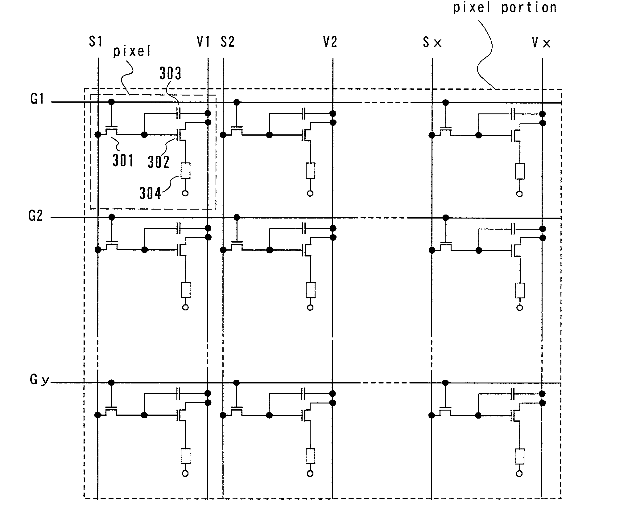
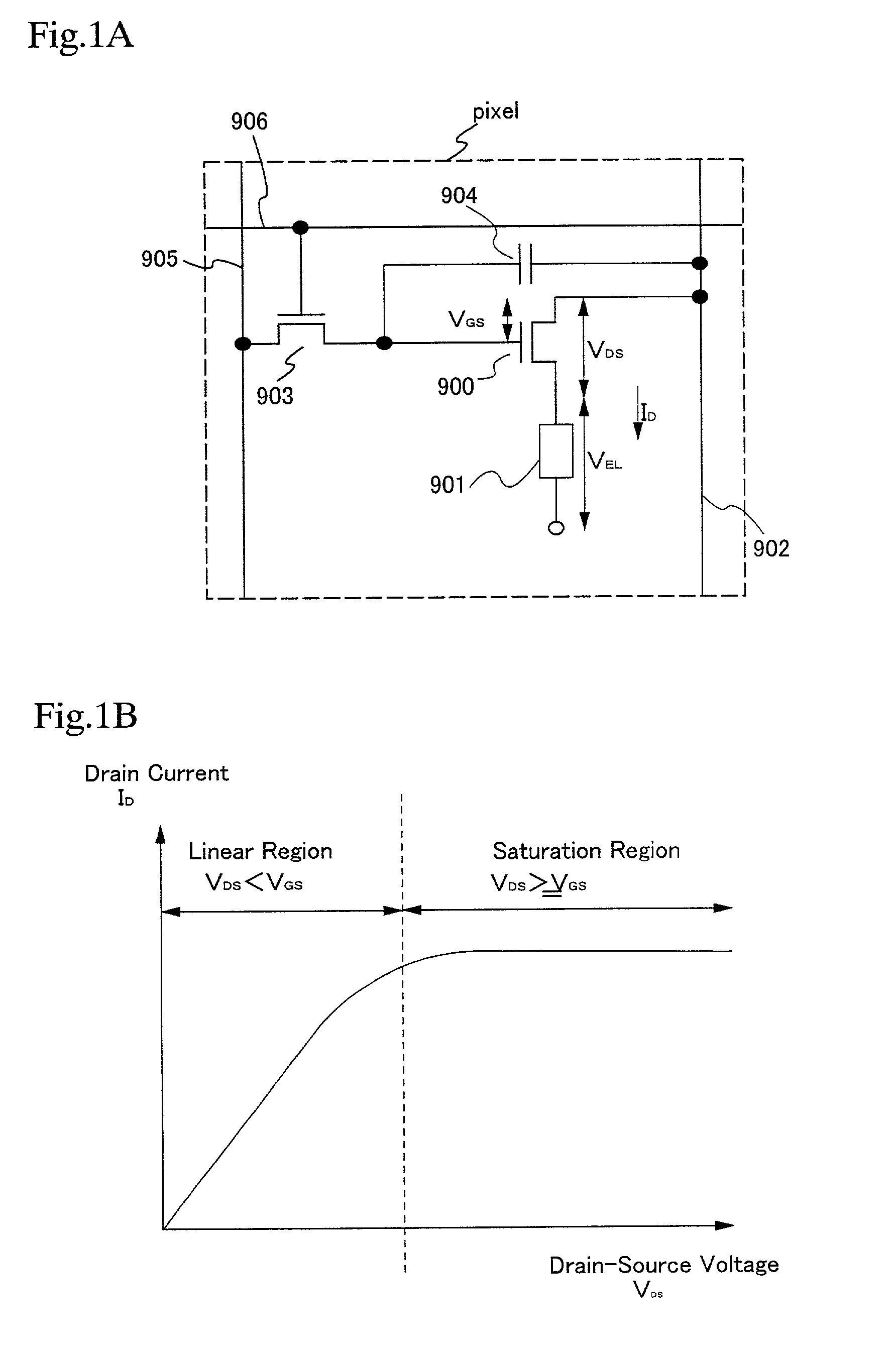
[0100] Embodiment 1 relates to the method in the above description of the embodiment mode of the present invention, i.e., the method of operating the EL driving TFT in the saturation region to keep constant the drain current I.sub.D which flows across both electrodes of the EL element, and the following description of Embodiment 1 is a method of suppressing the influence of the unevenness of the characteristics of EL driving TFTs. The following description uses the same reference numerals and used in FIG. 1A as well as newly added ones.

[0101] In the case where the EL driving TFT 900 is operated in the saturation region, the following equation (1) is obtained:

I.sub.D=.alpha.(W / L)(V.sub.GS-V.sub.th).sup.2 (1)

[0102] In equation (1), I.sub.D is the drain current, V.sub.GS is the gate voltage, V.sub.th is the threshold voltage, W is the gate width, L is the gate length, and .alpha. is a constant. In this case, since the threshold voltage V.sub.th has variations, the ...

embodiment 2

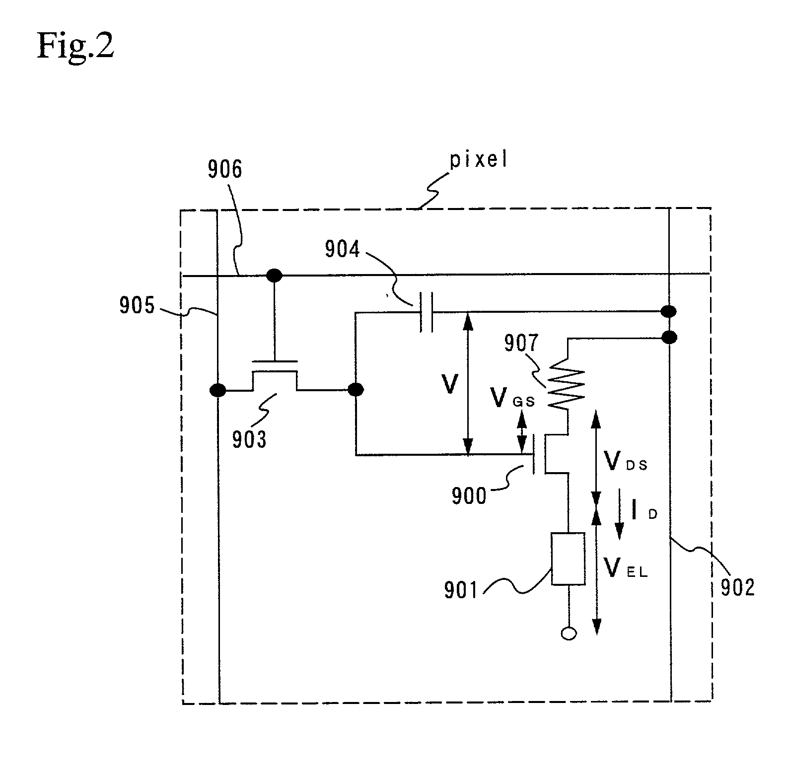
[0107] (Embodiment 2)

[0108] Embodiment 2 relates to the method in the above description the embodiment mode of the present invention, i.e., the method of operating the EL driving TFT in the saturation region to keep constant the drain current I.sub.D which flows across both electrodes of the EL element, and the following description of Embodiment 2 is a method of suppressing the influence of the unevenness of the characteristics of EL driving TFTs by a method different from that used in Embodiment 1.

[0109] FIG. 2 is a circuit diagram showing the construction of a pixel portion of an EL display device according to Embodiment 2. The pixel portion shown in FIG. 2 is the same in basic structure as that shown in FIG. 1A, and in the following description, the modified portions of the construction shown in FIG. 1A are denoted by different reference numerals.

[0110] The gate electrode of the switching TFT 903 is connected to the gate signal line 906. Either one of the source and drain region...

embodiment 3

[0120] (Embodiment 3)

[0121] Note that a description is set forth regarding a step for fabricating TFTs for driver circuit (a source signal line driver circuit and a gate signal line driver circuit) provided in the pixel portion of a display device using the driver method of the present invention and periphery portion of the pixel portion. For the simplicity of the explanation, a CMOS circuit is shown in figures, which is a fundamental structure circuit for the driver circuit portion.

[0122] First, as shown in FIG. 8A, a base film 5002 made of an insulating film such as a silicon oxide film, a silicon nitride film, or a silicon oxynitride film, is formed on a substrate 5001 made of a glass such as barium borosilicate glass or aluminum borosilicate glass, typically a glass such as Corning Corp. #7059 glass or #1737 glass. For example, a lamination film of a silicon oxynitride film 5002a, manufactured from SiH.sub.4, NH.sub.3, and N.sub.2O by plasma CVD, and formed having a thickness of...


PUM


Abstract

An active matrix type EL display device is provided, which is capable of suppressing the unevenness of luminance display due to the unevenness of the characteristics of TFTs which constitute pixels, or due to variations in the environmental temperature at which the display device is used. The active matrix type EL display is driven by a time gray scale method, and is capable of keeping the drain current of each of its EL driving TFTs constant by operating each of the EL driving TFTs in a saturation region in an ON state. Accordingly, constant current can be made to flow in each of the EL elements, whereby it is possible to provide an active matrix type EL display device with accurate gray scale display and high image quality.

Description

[0001] 1. Field of the Invention[0002] The present invention relates to a method of driving an electronic display device having EL (electro luminescence) elements formed on a substrate. More particularly, the invention relates to a method of driving an EL display device using semiconductor elements (elements using semiconductor thin films) as well as to electronic equipment of the type in which an EL display device is used as a display part.[0003] Incidentally, the term "EL element" used herein indicates both an element which uses emission from a singlet exciter (fluorescence) and an element which uses emission from a triplet exciter (phosphorescence).[0004] 2. Description of the Related Art[0005] In recent years, in the field of self-emitting elements, the development of EL display devices having EL elements has been becoming more and more active. EL display devices are called organic EL displays (OELD(s)) or organic light emitting diodes (OLED(s)).[0006] Such an EL display device ...

Claims


Application Information

Patent Timeline
Patent Type & Authority Applications(United States)
IPC IPC(8): G09G3/20G09G3/32H01L27/32
CPCG09G3/2014G09G3/30G09G3/3233G09G3/3275G09G3/3291G09G2300/0417G09G2300/0426G09G2300/0814G09G2300/0842G09G2300/0866G09G2320/0233G09G2320/041G09G2320/043H01L27/322H01L27/3244H01L2251/5315G09G3/2022H10K59/38H10K59/12H10K2102/3026H10K59/123H10K50/11H10K59/131H10K2101/10G09G3/2003G09G2330/02H01L27/1255
Inventor KOYAMA, JUN
Owner SEMICON ENERGY LAB CO LTD
Why Eureka
Try Eureka