Articles with selectively deposited overlay

Inactive Publication Date: 2002-05-30
JAEGER PETER
View PDF0 Cites 3 Cited by
  • Summary
  • Abstract
  • Description
  • Claims
  • Application Information

AI Technical Summary

Problems solved by technology

Decorative overlays of silver and other metals have been applied to glass and other electrically non-conductive surfaces in the past, but these have not been entirely satisfactory because of the relatively poor adhesion of the metal plating to the glass or other non-conductive material such as plastic.
The metal is held on the non-conductive surface by an adhesive, and when the surface of the metal is

Method used


Image

  • Articles with selectively deposited overlay
  • Articles with selectively deposited overlay

Examples


Embodiment Construction

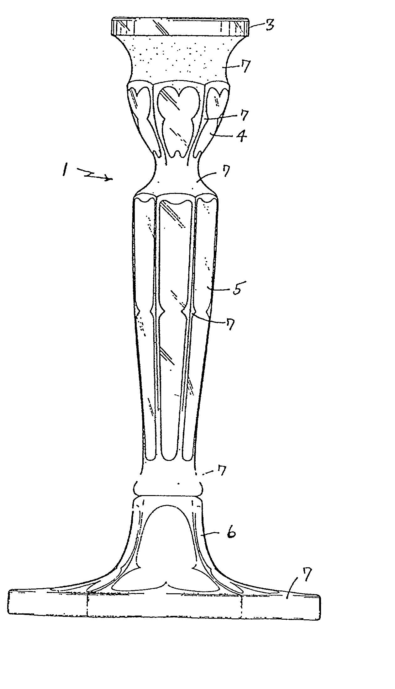
[0018] The invention is particularly useful for decorating a three-dimensional surface and will be described in connection with the preferred embodiment in which a decorative metal layer is applied to a glass candle stick holder of the type having a flared, multi-angular base, or pedestal, from which a tapered, six sided stem extends upwardly to a candle receiver which is circular in cross-section. Peripheral grooves are between the base and the stem and between the stem and the candle receiver. It will be apparent that decoration must conform to many different surfaces which intersect at various angles. The methods of the invention permits the application of an aesthetic metal pattern to such a candle stick holder.

[0019] The glass candle stick holder 1 shown in FIG. 1 has surface areas 3-6 of bare glass with a decorative pattern of shiny metal areas 7 thereon produced in accordance with the invention.

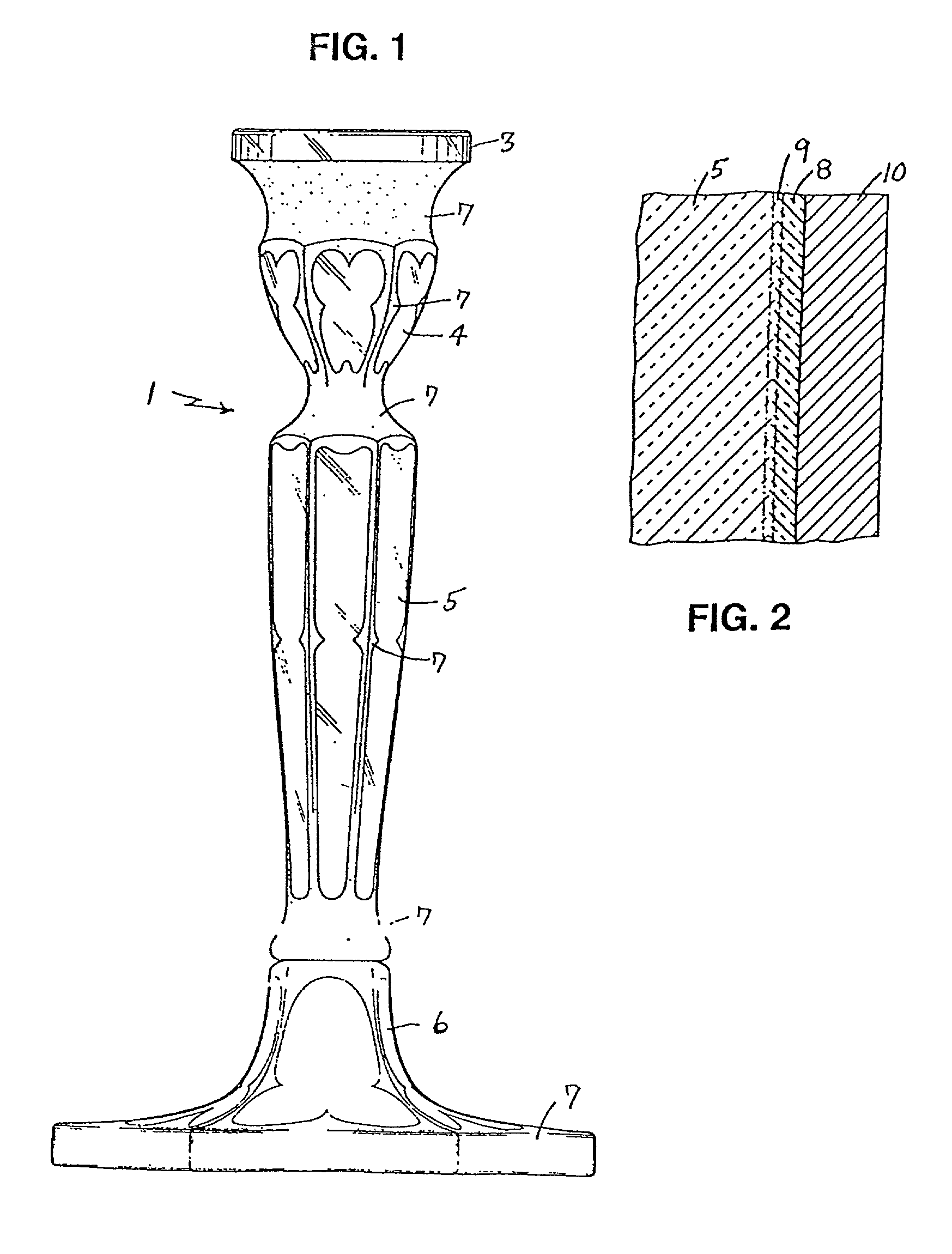
[0020] FIG. 2 is an enlarged, fragmentary cross-section of a typical layer of meta...


PUM

PropertyMeasurementUnit
Fractionaaaaaaaaaa
Percent by volumeaaaaaaaaaa
Mesh sizeaaaaaaaaaa

Abstract

A method of providing a decorative metal pattern on an electrically non-conductive substrate, such as a glass or plastic substrate, which includes applying a mixture of a heat fusible material, such as glass or plastic, with a metal having a particle size less than about 500 mesh constituting at least 50% of the mixture, to the substrate in the desired pattern, heating the so-applied mixture until the heat fusible material fuses and bonds to the substrate, cleaning the substrate with the pattern thereon, and electroplating the pattern with the desired finish metal. In one method in which the mixture-includes glass, a negative resist is adhesively secured to the substrate and the mixture is applied. The resist disintegrates upon heating. In another method, used when the substrate is plastic, a mixture of plastic and metal in paste form is applied to the substrate by silk screening or pad printing to form the pattern. In both cases, the pattern is bonded to the substrate by intermolecular bonding and has sufficient conductivity for electroplating without intermediate processing. Also, articles produced by such methods.

Description

[0001] This Application is a Divisional Application of U.S. application Ser. No. 08 / 636,787 filed on Apr. 23,1996, incorporated herein by reference.DESCRIPTION OF RELATED ART[0002] Decorative overlays of silver and other metals have been applied to glass and other electrically non-conductive surfaces in the past, but these have not been entirely satisfactory because of the relatively poor adhesion of the metal plating to the glass or other non-conductive material such as plastic. Generally speaking, such metal patterns have been applied by hand, e.g. with brushes, by silk screening, or by metal leaf. The metal is held on the non-conductive surface by an adhesive, and when the surface of the metal is rough, such as with brush application, the metal cannot be adequately polished without damaging the metal pattern.[0003] The metal pattern has also been applied by electroplating, and in such method, conductive areas in the shape of the desired pattern are formed on the base, non-conduct...

Claims


Application Information

Patent Timeline
IPC IPC(8): C25D5/02C25D5/54
CPCC25D5/022C25D5/54Y10T428/12597Y10S65/05Y10T428/24917Y10S65/10C25D5/56
Inventor JAEGER, PETER
Owner JAEGER PETER
Why Eureka
Try Eureka