
Electrode for lithium secondary battery and lithium secondary battery

a lithium secondary battery and electrode technology, applied in the manufacture of negative electrodes, cell components, electrode manufacturing processes, etc., can solve the problems of inability to obtain disadvantageously sufficient cycle characteristics, inability to easily obtain a foil having a practical thickness, and the surface roughness ra which exceeds 2 .mu.m

Inactive Publication Date: 2002-07-04
SANYO ELECTRIC CO LTD
View PDF0 Cites 31 Cited by
  • Summary
  • Abstract
  • Description
  • Claims
  • Application Information

AI Technical Summary

Benefits of technology

[0011] In the present invention, the surface roughness Ra and an average interval S between local tops of the current collector preferably satisfy a relationship given by: 100Ra.gtoreq.S. When the relationship is satisfied, the charge / discharge cycle characteristics can be further improved.
[0015] In the present invention, the alloy thin film containing Sn and In can be used as an active material. Such an alloy thin film is used as the active material to make it possible to achieve charge / discharge cycle characteristics which are better than those obtained when a metal thin film consisting of only, e.g., Sn is used as an active material. It is supposed that the use of the alloy thin film containing In can moderate stress generated in the active material thin film when expansion and shrinkage of the active material thin film occurring with charging / discharging.

Problems solved by technology

However, lithium is precipitated in the form of a dendrite in a charging state to disadvantageously cause an internal short circuit.
However, when these metals which are alloyed with lithium (Li) are used as negative electrode materials, the materials considerably increase or reduce in volume with absorption and release of lithium, the electrode active materials are pulverized to be eliminated from a current collector, so that sufficient cycle characteristics cannot be obtained disadvantageously.
Although the maximum value of the surface roughness Ra is not limited to a specific value, a current collector having a surface roughness Ra which exceeds 2 .mu.m cannot be easily obtained as a foil having a practical thickness.

Method used


Image

  • Electrode for lithium secondary battery and lithium secondary battery
  • Electrode for lithium secondary battery and lithium secondary battery

Examples


Embodiment Construction

[0023] The present invention will be described below with reference to an embodiment. However, the present invention is not limited to the following embodiment, and various modifications of the present invention can be effected without departing from the spirit and scope of the invention.

[0024] [Fabrication of Electrode]

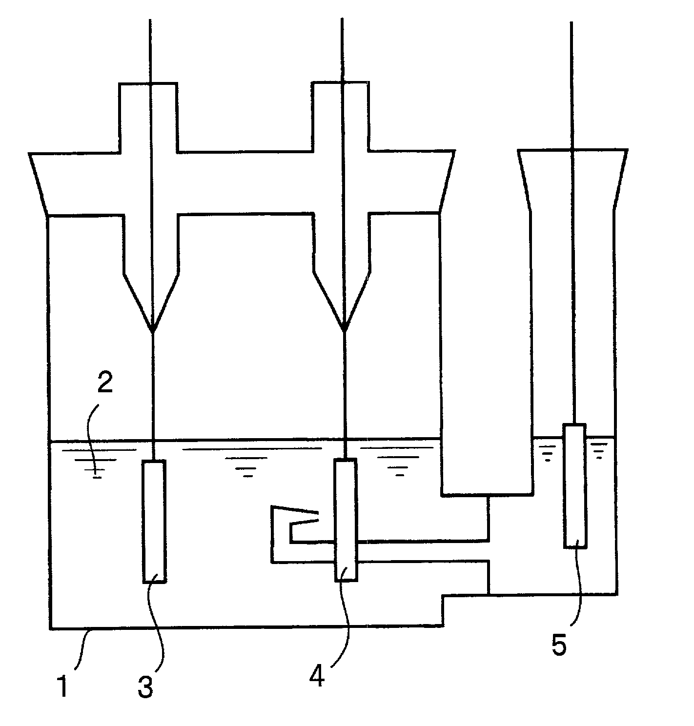
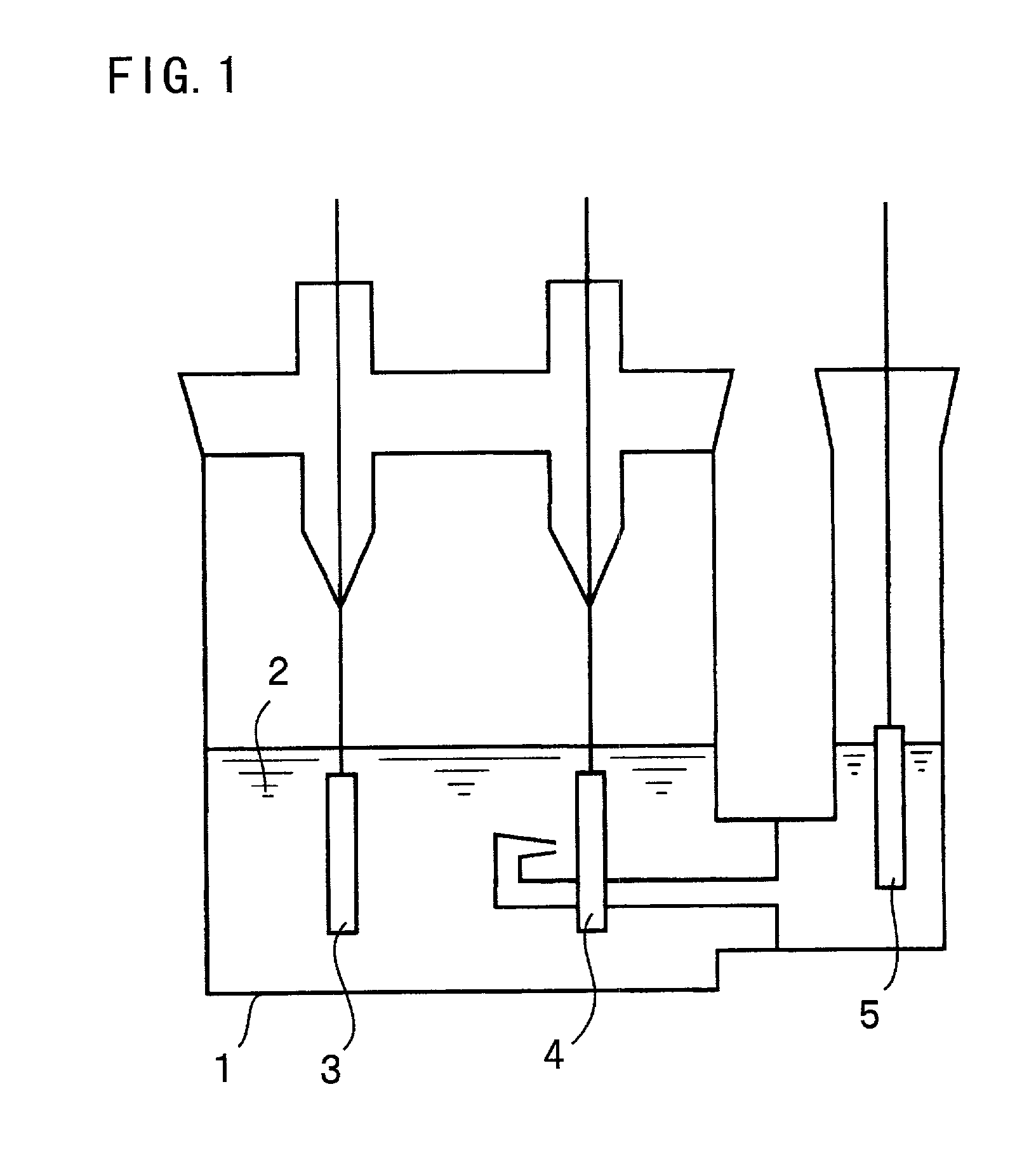
[0025] Four types of copper foils were used as current collectors, and alloy thin films each consisting of Sn and In and each having a thickness of 2 .mu.m were formed on surfaces having predetermined surface roughness Ra (to be described below) by an electrolytic plating method. As the copper foils, an electrolytic copper foil A (surface roughness Ra=0.19 .mu.m and an average interval S between local tops=1.8 .mu.m), an electrolytic copper foil B (surface roughness Ra=0.60 .mu.m and an average interval S between local tops=2.2 .mu.m), an electrolytic copper foil C (surface roughness Ra=1.19 .mu.m and an average interval S between local tops=1.9 .mu.m), and a rolled ...


PUM

PropertyMeasurementUnit
Percent by massaaaaaaaaaa
Fractionaaaaaaaaaa
Fractionaaaaaaaaaa

Abstract

An electrode for a lithium secondary battery in which an alloy thin film containing Sn (tin) and In (indium) is formed on the surface of a current collector having a surface roughness Ra of 0.1 mum or more, and a lithium secondary battery using thereof.

Description

[0001] 1. Field of the Invention[0002] The present invention relates to a novel electrode for a lithium secondary battery and a lithium secondary battery using thereof.[0003] 2. Related Art[0004] Lithium secondary batteries which are vigorously studied and developed in recent years have battery characteristics such as charge / discharge voltages, charge / discharge cycle life characteristics, and storage characteristics which are considerably dependent on electrodes used in the lithium secondary batteries. For this reason, the improvements in the electrodes active materials are attempted to enhance battery characteristics.[0005] When a lithium metal is used as a negative-electrode active material, batteries having high energy densities per weight and per volume can be constituted. However, lithium is precipitated in the form of a dendrite in a charging state to disadvantageously cause an internal short circuit.[0006] On the other hand, lithium secondary batteries which use, as an electr...

Claims


Application Information

Patent Timeline
IPC IPC(8): C22C13/00C22C28/00H01M4/134H01M4/1395H01M4/38H01M4/66H01M10/05
CPCH01M4/04H01M4/0461H01M4/13H01M4/382H01M4/661H01M4/667H01M10/052H01M2004/021H01M2004/027Y02E60/122Y10T29/10H01M4/38H01M4/387Y02E60/10
Inventor TAMURA, NORIYUKIJITO, DAIZOOHSHITA, RYUJIFUJIMOTO, MASAHISAKAMINO, MARUOFUJITANI, SHIN
Owner SANYO ELECTRIC CO LTD
Learn More