
Thermal interface

a technology of thermal control system and interface, which is applied in the direction of sealing, lighting and heating apparatus, and semiconductor/solid-state device details, etc., can solve the problems of limiting the overall performance of the thermal control system, the fiber tip is not flat, and the promise of the technology has not been realized

Inactive Publication Date: 2002-08-01
KULR TECH
View PDF65 Cites 81 Cited by
  • Summary
  • Abstract
  • Description
  • Claims
  • Application Information

AI Technical Summary

Problems solved by technology

While individual components might have very high conductance, large temperature drops (.DELTA.T's) can develop at high resistance interfaces, limiting overall performance of the thermal control system.
Although carbon fiber based gaskets have increased thermal conductance over many other alternatives, their promise has not been realized, and further improvements to the efficiency of heat transfer for these types of gaskets is needed.
In addition, the fiber tip is not flat, being highly irregular in shape.
Because the nanofibril powder is not an aligned array of nanofibrils, there are many inter fibril interfaces which still interfere with efficient heat transfer.
rs. However, they tend to have a high defect density, exemplified by their not being straight, and causing them to have a lower thermal conductivity than id

Method used

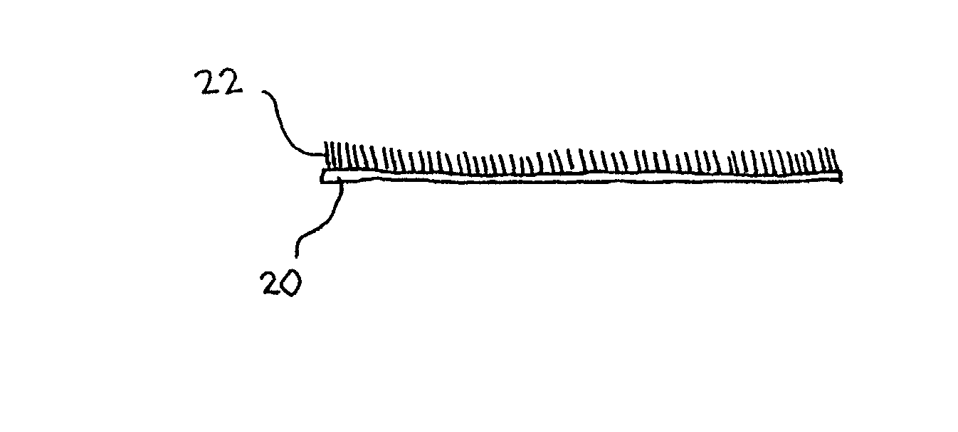

Image

  • Thermal interface
  • Thermal interface
  • Thermal interface

Examples


Embodiment Construction

[0058] Pitch carbon fiber gasket sample cs7-144 was processed in the PE-HF CVD reactor under the conditions listed in Table 1

1TABLE 1 PE-HF CVD deposition conditions of pitch fiber gasket sample Sample# cs7-144 Mounting Lying flat on anode conditions Plasma power 160 W HF power 300 W Max temperature 527.degree. C. Plasma etch time 12 min Deposition time 5 min Hydrocarbon gas Acetylene Mass gain 4.6 mg (5%) Resulting deposit Heavy, bottom side

[0059] After the chamber cooled, the sample was removed and examined under the microscope. The bottom of Sample cs7-144 was covered with carbon deposit that was visible under the optical microscope. The 90.5 mg sample had gained 4.6 mg, which corresponds to a 4 micron-thick, uniform layer of carbon over one surface. Some areas displayed thicker deposits than others. The variation may reflect variation in local temperature, hydrocarbon concentration, and / or catalyst microstructure.

[0060] FIG. 5 is a 250.times. SEM image of a pitch carbon fiber ga...


PUM

PropertyMeasurementUnit
Diameteraaaaaaaaaa
Diameteraaaaaaaaaa
Lengthaaaaaaaaaa

Abstract

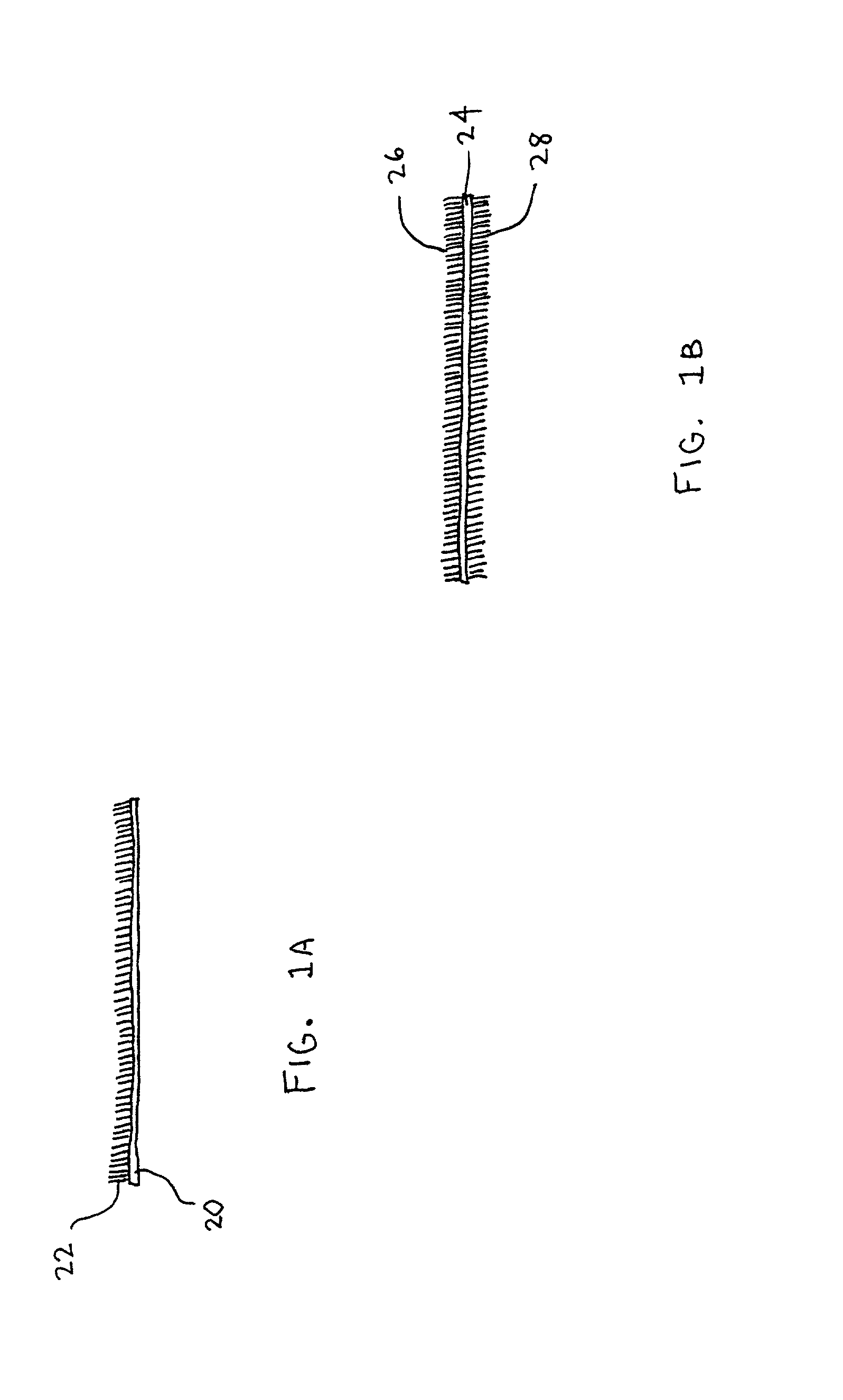
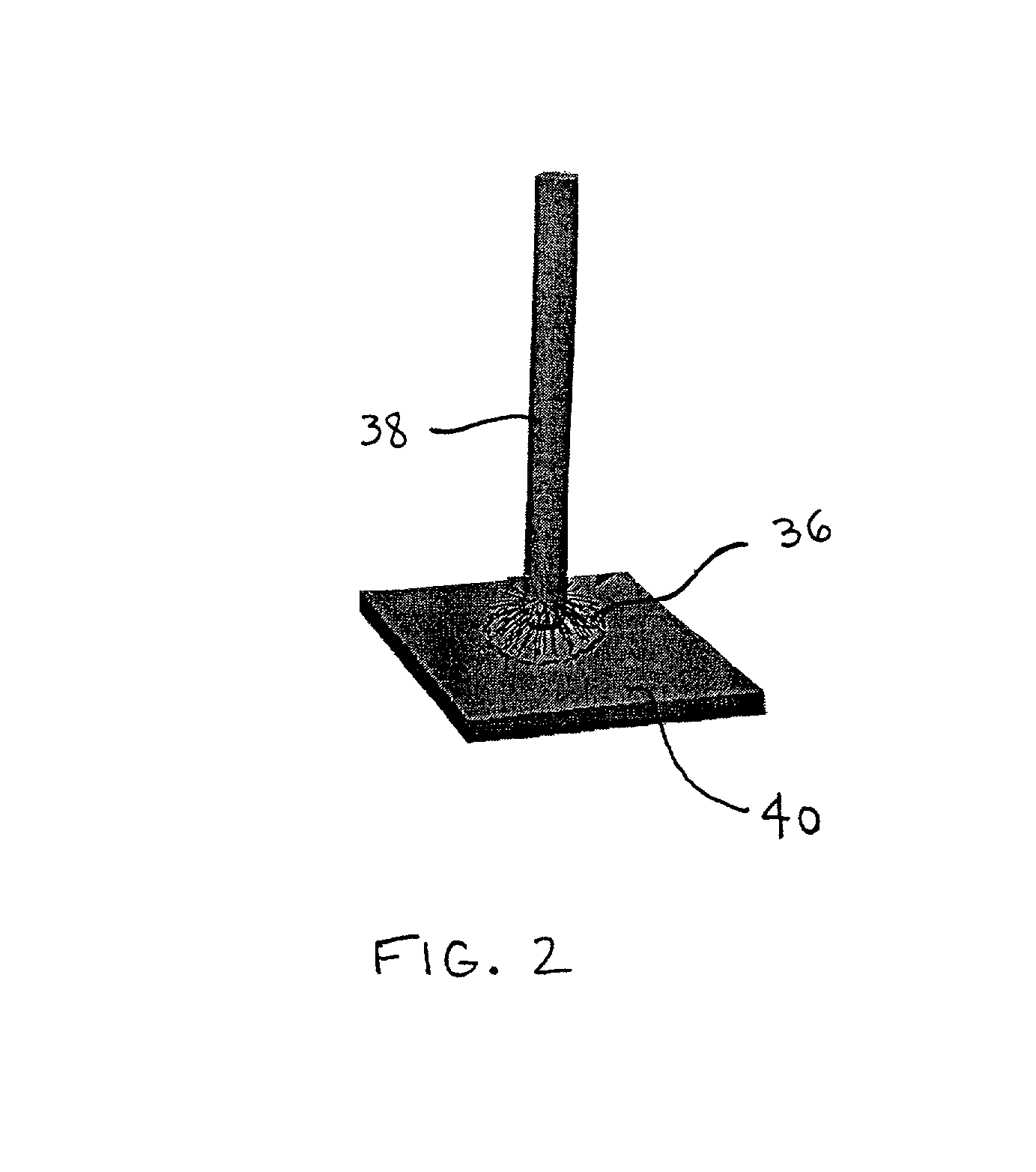
A thermal interface includes nanofibrils. The nanofibrils may be attached to a flat base or membrane, or may be attached to the tip portions of larger diameter fibers. The nanofibrils have a diameter of less than about 1 micron, and may advantageously be formed from single walled and / or multi-walled nanotubes.

Description

[0001] This application is a continuation of U.S. patent application Ser. No. 09 / 593,587, entitled Thermal Interface, filed on Jun. 13, 2000, which claims priority to U.S. Provisional Patent Application Serial No. 60 / 139,443, entitled Thermal Interface, and filed on Jun. 14, 1999. The entire disclosures of both applications are hereby incorporated by reference in their entirety.[0002] 1. Field of the Invention[0003] The invention relates to heat transfer interfaces such as gaskets that provide a path for heat transfer between two surfaces.[0004] 2. Description of Related Art[0005] Much of thermal management involves the transfer of heat from one element, such as electronic components, boards and boxes, heatpipes, radiators, heat spreaders, etc. to another. Of major concern in this process is the thermal contact resistance of the interface between the two components. While individual components might have very high conductance, large temperature drops (.DELTA.T's) can develop at high...

Claims


Application Information

Patent Timeline
IPC IPC(8): F28F3/02H01L23/36H01L23/373H01L23/427
CPCB82Y10/00C23C16/0281C23C16/26F28F3/022H01L23/36H01L23/3733H01L23/4275H01L2924/3011Y10S977/742Y10S977/734Y10S165/905Y10S277/938Y10S977/753H01L2924/0002H01L2924/00Y10T428/2935Y10T428/2913Y10T428/298Y10T428/2918H01L23/373
Inventor KNOWLES, TIMOTHY R.SEAMAN, CHRISTOPHER L.
Owner KULR TECH
Learn More