Optical disk device

a technology of optical disk and optical disk, which is applied in the direction of digital signal error detection/correction, instruments, recording signal processing, etc., can solve the problems of decreasing productivity, increasing manufacturing costs, and degrading recording/reproducing characteristics, and achieves stable and high-density effects

Inactive Publication Date: 2002-08-22
NEC CORP
View PDF15 Cites 20 Cited by
  • Summary
  • Abstract
  • Description
  • Claims
  • Application Information

AI Technical Summary

Benefits of technology

0029] It is also possible to compensate for the aspheric aberration caused by the thickness error of the transparent substrate based on the detected thickness error, by placing aspheric aberration compensators on the optical paths of the signal detectors.
0030] It is also possible to compensate for aspheric aberration in order to provide stable, high-density recording and reproduction even if the thickness of the transparent substrate varies with the radial position, by providing a con

Problems solved by technology

Furthermore, information recording or reproducing are normally carried out by irradiating the recording/reproducing surface with optical beams through a transparent substrate, which serves as the protective layer, so that spherical aberrations occur if the thickness of the transparent substrate deviates from the specified value and causes degradation in the recording/reproducing characteristics.
However, since all of these prior

Method used


Image

  • Optical disk device
  • Optical disk device
  • Optical disk device

Examples


first embodiment

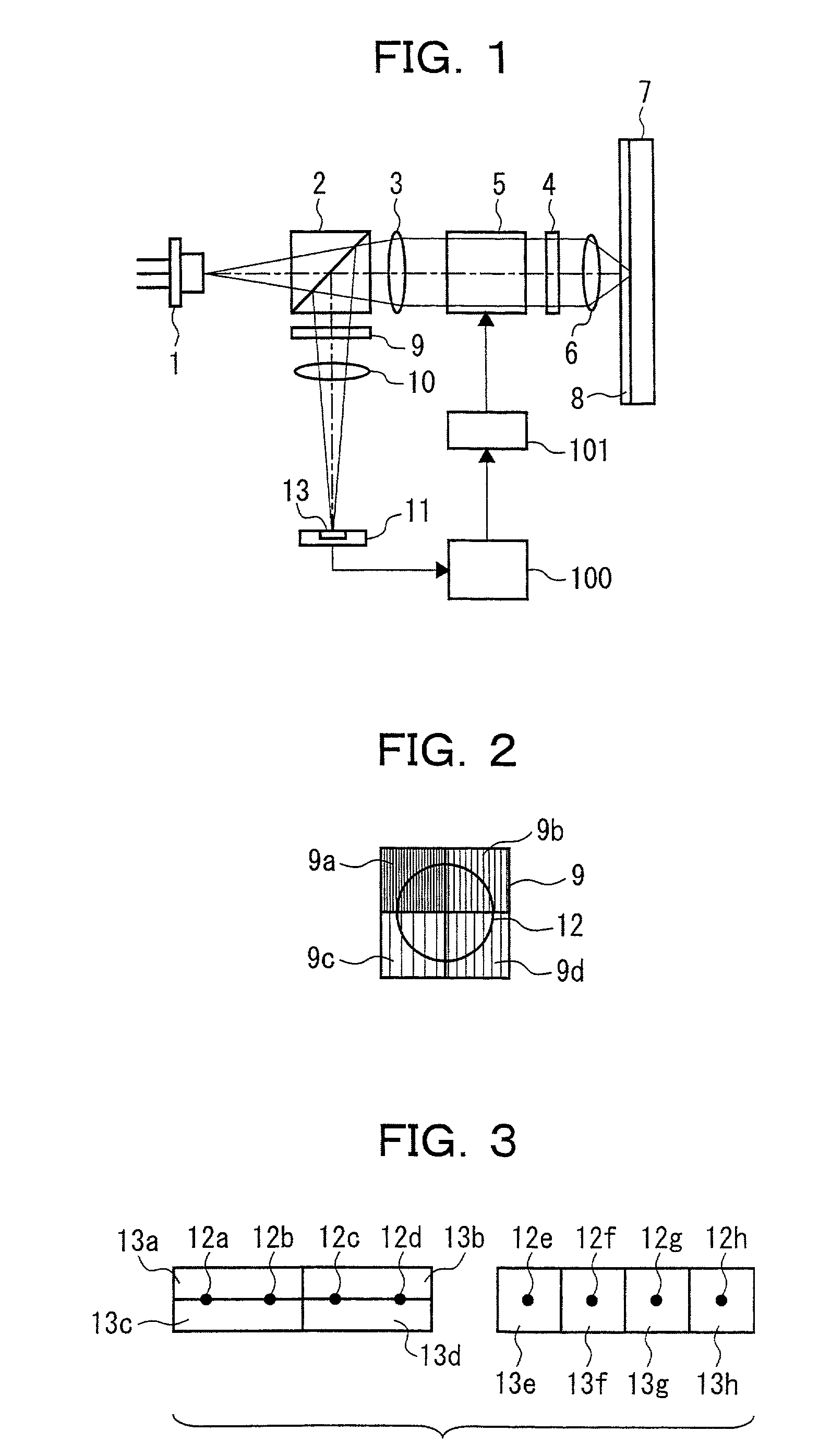
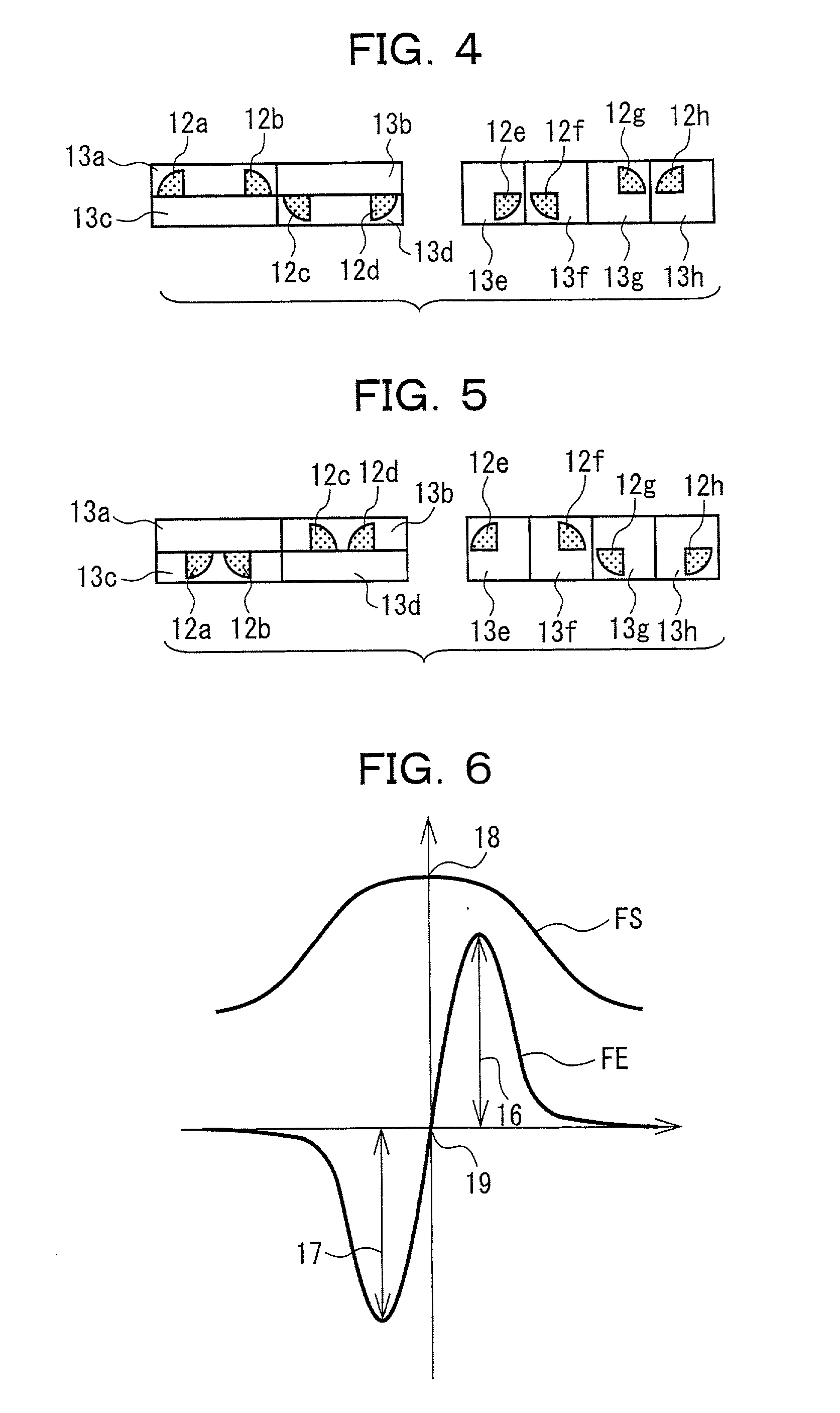
[0053] Embodiments of the present invention will be described below in detail with reference to the accompanying drawings. FIG. 1 shows the present invention. FIG. 1 shows an optical disk device for recording / reproducing information on an optical disk with a recording layer formed on a transparent substrate, having a typical construction for detecting focus error signals that detect the deviations of condensing points of light beams condensing on the recording / reproducing surface by means of the knife-edge method. The principle of detecting the thickness error of the transparent substrate in the optical disk device as shown in FIG. 1 using the focus error signal detection system of the knife-edge method will be described below.

[0054] First, the construction of FIG. 1 and the principle of the focus error signal detection according to the knife-edge method will be described. A light beam released from a laser diode 1 passes through a polarizing light beam splitter 2, becomes a paralle...

third embodiment

[0113] Next, we will describe the optical disk according to the present invention with reference to FIG. 16. FIG. 16 shows a general construction of the optical disk device for recording or reproducing information on the optical disk with a recording layer formed on a transparent substrate, in which the focus error signal is obtained by detecting the condensing point deviation of the light beams condensing on the recording or reproducing surface based on the astigmatism method. We will discuss below the principle of the process of detecting the thickness error of the transparent substrate in the optical disk device shown in FIG. 16 using the focus error signal detection system based on the astigmatism method.

[0114] First, the construction shown in FIG. 16 and the principle of the focus error signal detection based on the astigmatism method are explained. A light beam released from a laser diode 42 passes through a polarizing light beam splitter 43, becomes a parallel light by means ...


PUM


Abstract

The invention detects the thickness error of the transparent substrate using a general focus error signal detection system employing the fact that the reflecting light from the optical disk causes distortions in diffraction image at the detection plane or unsymmetrical expansions before and after the detection plane due to spherical aberration as a result of thickness errors of the transparent substrate. The absolute amount of the thickness error of the transparent substrate and its symbol are detected by detecting the difference between the absolute value of the positive side peak and the absolute value of the negative side peak of the focus sum signal, or the difference in focus positions between the peak point of the focus sum signals and the zero point of the focus error signals using the focus error signal detection system according to the knife-edge method. This enables it to detect the thickness error of the transparent substrate without using a special optical system.

Description

[0001] 1. Technical Field of the Invention[0002] The present invention relates to an optical disk device for recording or reproducing information, in particular, to an optical disk device capable of detecting a thickness error of the transparent substrate of the optical disk.[0003] 2. Description of the Related Art[0004] The optical disk device typically used in CD (compact disk) and DVD (digital versatile disk) devices as a means of recording or reproducing information using light is widely used as an information recording device for images, sound and computer data, and demand for increasing its density and capacity has constantly intensified in recent years. The recording density of an optical disk device can be effectively increased by reducing the spot diameters of optical beams condensed on the recording / reproducing surface by means of lowering the wavelength of the source light and increasing the numerical aperture (NA) of the objective lens mounted on the optical head that wr...

Claims


Application Information

Patent Timeline
IPC IPC(8): G11B7/085G11B7/09G11B7/125G11B7/13G11B7/131G11B7/133G11B7/135G11B7/1369G11B7/1372G11B7/1378G11B7/1392
CPCG11B7/0909G11B7/0912G11B7/0916G11B7/131G11B7/133G11B7/1369G11B7/1378G11B7/13927G11B2007/13727
Inventor SHIRAKAWA, HIDEKAZUKATAYAMA, RYUICHI
Owner NEC CORP
Why Eureka
Try Eureka