Method and system for hot wire welding

a technology of method and system, applied in the field can solve the problems of introducing many errors, burning back, and affecting the quality of hot wire welding, and the prior art system does not provide coordinated control of components with respect to other components

Inactive Publication Date: 2002-08-29
ARNDT TONY LEE +2
View PDF0 Cites 58 Cited by
  • Summary
  • Abstract
  • Description
  • Claims
  • Application Information

AI Technical Summary

Problems solved by technology

This prior art system does not provide coordinated control of components with respect to other components.
This operation raises the possibility of introducing many errors.
For example, an excessively high hot wire voltage results in the burning back or premature melting of the wire within the wire feed conduit or nozzle; this causes damage to the feeding system.
On the other hand, if there is insufficient hot wire voltage applied for a certain wire feed speed, the wire will not adequately melt into the weld puddle, and in some cases will shoot through the welding arc.
Another prior art problem is magnetic interference or "Arc Blow" caused by the AC voltage or high DC voltage applied to the filler wire by the constant voltage power source 14.
Magnetic interference causes the main welding arc to wander and not maintain a consistent location at the desired welding position.
However, pulsing of the main weld current may not be ideal for the type of weld being done.
As slower wire feed speeds are introduced, the resulting hot wire voltage is increased, due to the fact that the wire is going in the puddle slower; this increases the amount of wire gap.
Some of the problems associated with the prior art system of FIG. 2 results from the complexity of the measuring and sensing circuitry needed to attempt to maintain a constant hot wire voltage.
Consequently, the torch area of the weld system becomes quite crowded, and this may not allow the torch to enter tight areas when needed.
However, this may not be the ideal situation for certain welding situations.

Method used


Image

  • Method and system for hot wire welding
  • Method and system for hot wire welding
  • Method and system for hot wire welding

Examples


Embodiment Construction

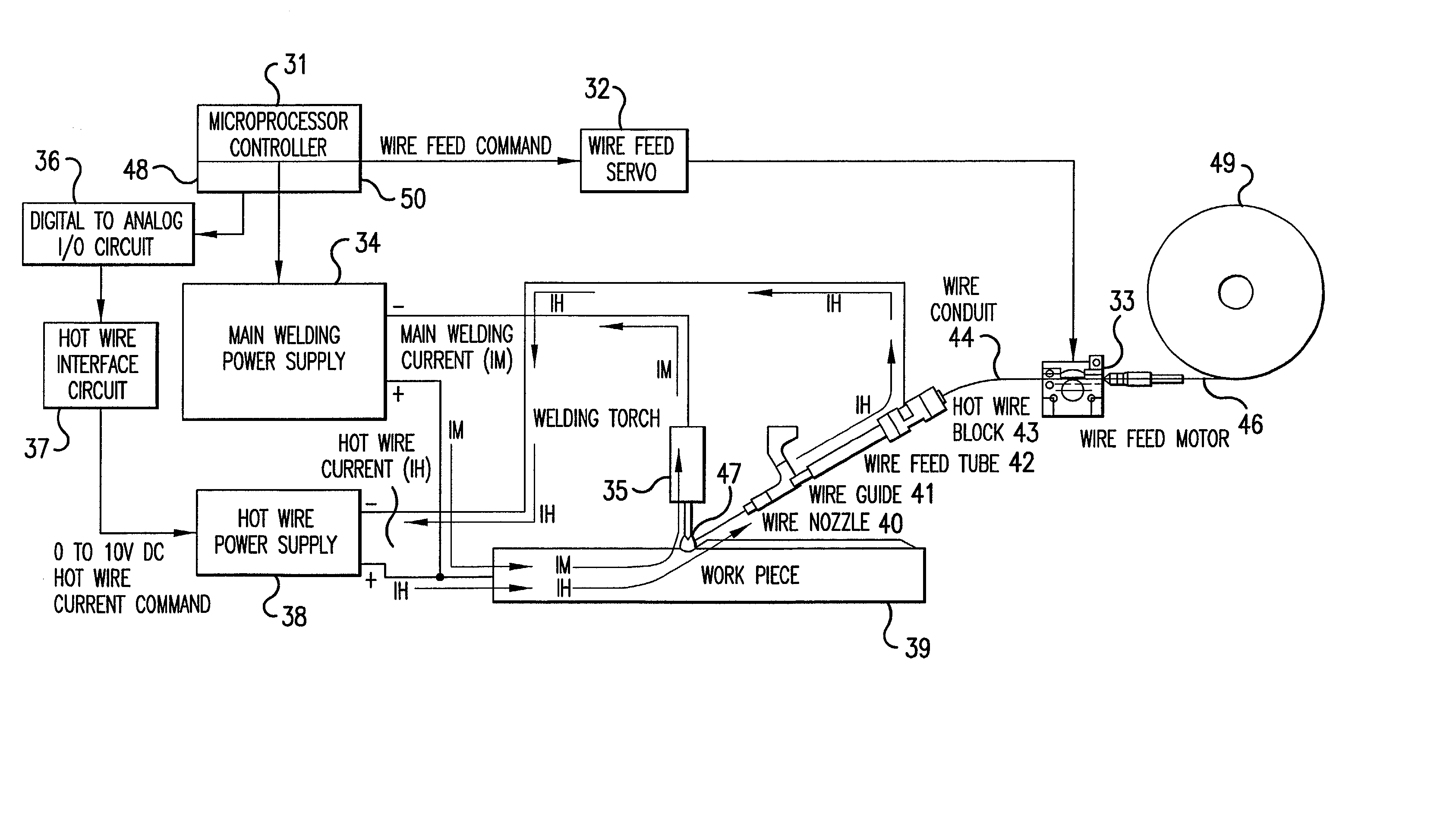
[0029] FIG. 3 is a block diagram of an embodiment of the present invention which provides simplified and easily overridden hot wire control. With reference to FIG. 3, digital computer means embodied as a microprocessor controller 31 is provided for controlling all aspects of the welding process. The microprocessor controller 31 comprises a central processing Unit (CPU) 48 for processing or running at least the logic routines provided in FIGS. 5 to 9, and a memory unit 50 for storing information including the data of FIG. 10 as a data-base. The CPU unit can include an Intel 8032 chip.

[0030] A wire feed servo 32 is directed by the microprocessor controller 31 to maintain a desired filler wire speed. A wire feed motor 33 feeds the filler wire 46 into a welding puddle 47. This system also contains a main welding power supply 34 for supplying a main welding current to a torch 35 which preferably includes a non-melting tungsten electrode. The main welding power supply 34 is preferably a D...


PUM

PropertyMeasurementUnit
DC output voltageaaaaaaaaaa
voltageaaaaaaaaaa

Abstract

A hot wire welding method and system rely upon a welding torch with a non-melting electrode, a melting metal filler wire that is fed into a weld puddle created by welding arc, a microprocessor controller for controlling (i) current of the main welding arc, (ii) filler wire feed speed, and (iii) hot wire current for heating the filler wire. The method and system also rely upon a main welding power supply for supplying the main welding arc and a secondary DC supply for supplying the hot wire current. The hot wire current is automatically controlled by the microprocessor to supply the correct amount of current to the filler wire in response to changes in wire feed speed.

Description

[0001] 1. Field of the Invention[0002] The present invention relates to hot wire welding. More specifically, the invention relates to a method and system for hot wire welding wherein control of the hot wire supply current is in direct relationship to the speed of the feed wire.[0003] 2. Description of the Prior Art[0004] The basic theory of Hot Wire (vs. Cold Wire) is to preheat the filler wire by running an electric current through it. The term "Hot Wire" is used because it is electrically hot, as well as physically hot. This allows a much higher disposition rate than conventional Cold Wire. The difference between the Hot Wire and Cold Wire systems is not striking until high feed rates are used. Generally, this rate will be above 130 inches per minute (IPM) for 0.035" wire or above 100 IPM for 0.045" wire. Many variables are involved, but typically with a Hot Wire system the amount of filler material added to the weld can be 2 to 4 times that for Cold Wire systems.[0005] With refer...

Claims


Application Information

Patent Timeline
Patent Type & Authority Applications(United States)
IPC IPC(8): B23K9/095B23K9/10B23K9/167
CPCB23K9/0953B23K9/1093B23K9/167
Inventor ARNDT, TONY LEEDIK, ROGER CARLKASKINEN, PELLERVO JOHNNES
Owner ARNDT TONY LEE
Why Eureka
Try Eureka