
Piezoelectric device

a piezoelectric ceramic and device technology, applied in the direction of generators/motors, impedence networks, basic electric elements, etc., can solve the problems of large poor high-temperature resistance, and inability to obtain high electromechanical coefficient by general manufacturing methods of piezoelectric ceramics, etc., to achieve low loss in high-frequency regions and high-temperature resistance. , the effect of low loss

Inactive Publication Date: 2002-09-12
MURATA MFG CO LTD
View PDF0 Cites 3 Cited by
  • Summary
  • Abstract
  • Description
  • Claims
  • Application Information

AI Technical Summary

Benefits of technology

[0010] Accordingly, a major object of the present invention is to provide a piezoelectric device having an electromechanical coefficient of not less than 20%, which can be practically used, by an energy-trapping effect using a piezoelectric ceramic having a layered perovskite structure provided with high-temperature resistance and little high-frequency loss.
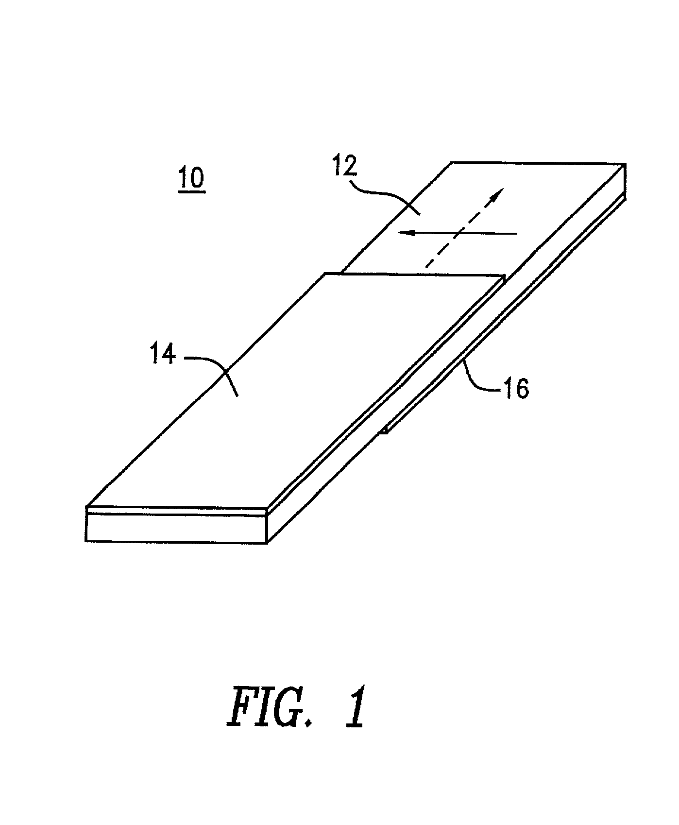
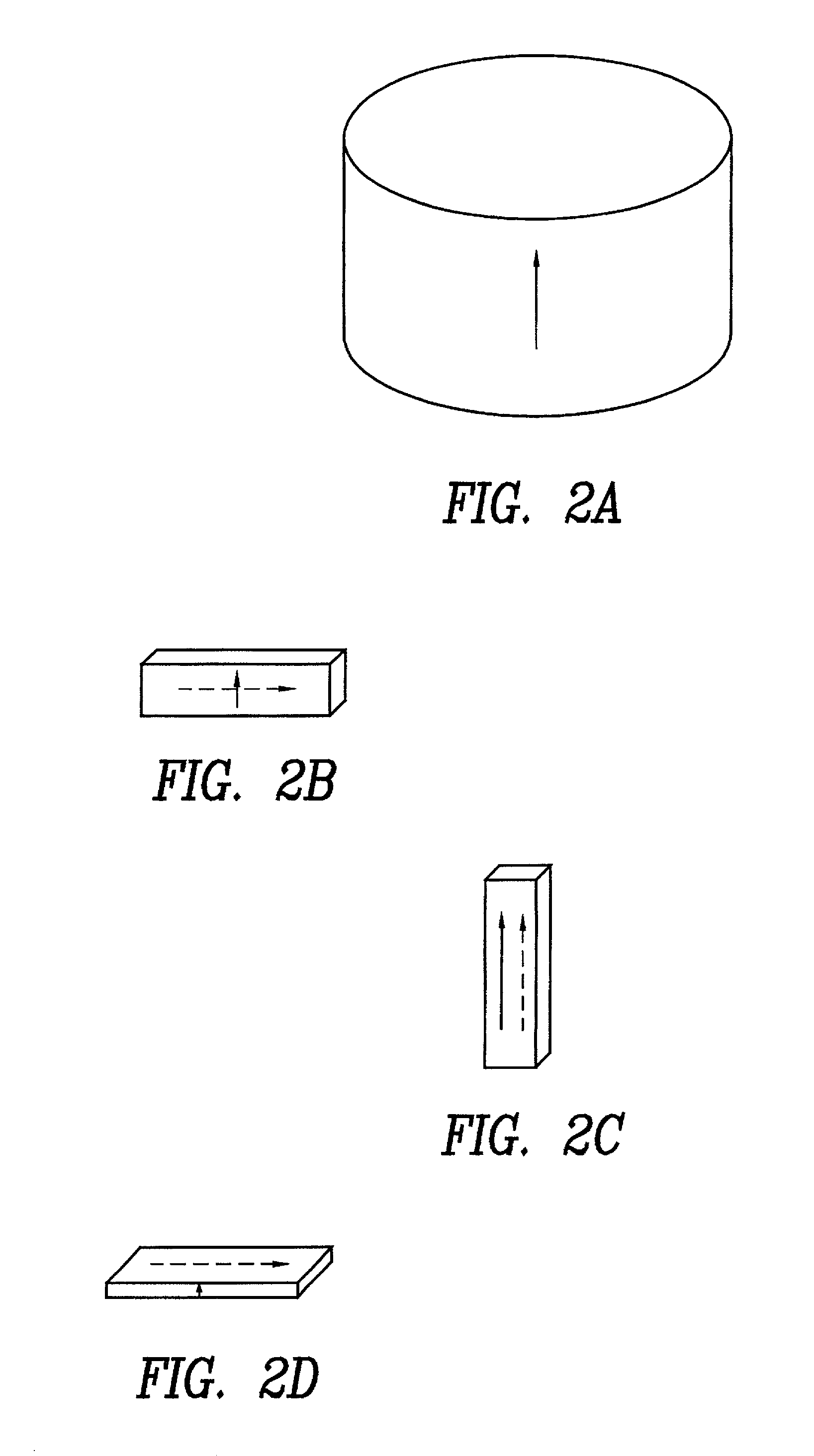
[0013] When the electrodes are formed on the substrate composed of a piezoelectric ceramic having a layered perovskite structure, and when the direction in which one crystal axis in the substrate is preferentially oriented approximately orthogonal to the direction in which the substrate is polarized, and the electrodes are formed on surfaces of the substrate which are approximately parallel to the direction in which the crystal axis in the substrate is preferentially oriented and are approximately parallel to the direction in which the substrate is polarized, a device having superior high-temperature resistance and little high-frequency loss can be obtained. In addition, the device thus obtained has an electromechanical coefficient which can be practically used.
[0014] In the piezoelectric device described above, when the piezoelectric ceramic composition is used, which is primarily composed of a ceramic composition represented by, specifically, the formula CaBi.sub.4Ti.sub.4O.sub.15, superior temperature stability of resonant frequency can be achieved.

Problems solved by technology

However, the piezoelectric ceramics have problems in that high-temperature resistance is poor and loss in high-frequency regions is large.
However, since the piezoelectric ceramics have strong anisotropic characteristics in the crystal, a high electromechanical coefficient cannot be obtained by a general manufacturing method for piezoelectric ceramics.
However, it has been known that when the Poisson ratio of a piezoelectric ceramic is one-third or less, vertical fundamental vibration cannot trap energy.
Poisson ratios of almost all piezoelectric ceramics having a layered perovskite structure, such as CaBi.sub.4Ti.sub.4O.sub.15 and PbBi.sub.4T4O.sub.15, are one-third or less, so that it is difficult to trap energy.
Consequently, even though a single vibration mode is obtained, application as a piezoelectric resonator is limited.
However, no experiments to trap energy of shear vibration have been performed using a piezoelectric ceramic having a layered perovskite structure in which the c-axis is preferentially oriented in one direction.

Method used


Image

  • Piezoelectric device
  • Piezoelectric device
  • Piezoelectric device

Examples


example

[0023] Example

[0024] After CaO, Bi.sub.2O.sub.3 and TiO.sub.2 were prepared as starting materials and were measured so as to form the composition CaBi.sub.4Ti.sub.4O.sub.15, the starting materials were wet-blended for 4 hours using a ball mill, and a mixture was obtained. After drying, the mixture was pre-baked at 900.degree. C. and was coarsely pulverized, and after adding an appropriate amount of an organic binder to the mixture, wet-pulverization was performed for 4 hours using a ball mill. The product thus prepared was sieved with a #40 sieve to control particle size. Next, the product was molded at a pressure of 1,000 kg / cm.sup.2 to form a cylinder having a diameter of 20 mm and a thickness of 10 mm, and the cylinder thus formed was heat treated at 600.degree. C. so as to remove the organic binder and obtain a pretreated product.

[0025] While the pretreated product was pressed in the thickness direction thereof at a total pressure of 1 ton by mono-axial pressing, the pretreated ...


PUM

PropertyMeasurementUnit
angleaaaaaaaaaa
thicknessaaaaaaaaaa
diameteraaaaaaaaaa

Abstract

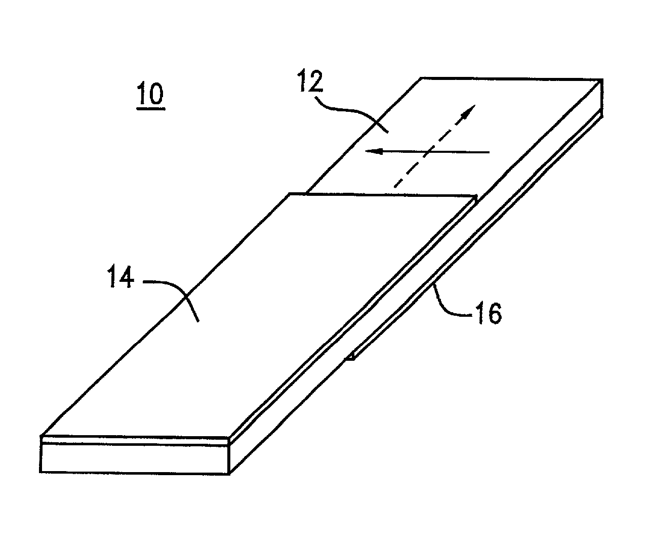
A piezoelectric device having an electromechanical coefficient, which can be applied to practical uses, is obtained by an energy-trapping effect using a piezoelectric ceramic having a layered perovskite structure provided with high-temperature resistance and little high-frequency loss. The piezoelectric device has a substrate formed of a piezoelectric ceramic having a layered perovskite structure. The c-axis in the substrate is preferentially oriented in the width direction thereof, and the substrate is polarized in the longitudinal direction. Two electrodes are formed on both main surfaces of the substrate so as to oppose each other in the vicinity of the central part thereof. As a material used for the substrate, a piezoelectric ceramic composition primarily composed of a ceramic composition represented by the general formula CaBi.sub.4Ti.sub.4O.sub.15 is preferably used.

Description

BACKGROUND OF THE INVENTION[0001] 1. Field of the Invention[0002] The present invention relates to piezoelectric devices, and more particularly, relates to a piezoelectric device used for, for example, an oscillator used in a filter for communication and in a clock generator.[0003] 2. Description of the Related Art[0004] Conventionally, as piezoelectric resonators for oscillators used in filters for communication and in clock generators, piezoelectric devices formed of piezoelectric ceramics primarily composed of lead titanate zirconate (Pb(Ti.sub.xZr.sub.1-x)O.sub.3) or lead titanate (PbTiO.sub.3) are widely used to employ the shear vibration of the piezoelectric ceramics. In general, the piezoelectric devices have substrates formed of rectangular piezoelectric ceramics and electrodes provided on both main surfaces of the substrate. The electrodes are not formed on the entire surfaces of the substrate, but are formed on parts of the surfaces so that parts of the electrodes oppose e...

Claims


Application Information

Patent Timeline
Patent Type & Authority Applications(United States)
IPC IPC(8): C04B35/46C04B35/00H01L41/08H01L41/09H01L41/187H03H9/17
CPCC04B35/475C04B35/6262C04B2235/3208C04B2235/604C04B2235/787H01L41/1878H03H9/02031H03H9/02157H03H9/177H10N30/8561H10N30/00
Inventor KIMURA, MASAHIKOANDO, AKIRASAWADA, TAKUYAOGAWA, HIROZUMI
Owner MURATA MFG CO LTD
Learn More