Distributed type switching system

a technology of distributed type and switching system, which is applied in the field of distributed type switching system, can solve the problems of inability to eliminate the limitation imposed on throughput, complexity of software, and inability to extend the throughput of a processor unlimitedly, and achieve the effect of high throughput and economics

Inactive Publication Date: 2002-09-12
HITACHI LTD
View PDF0 Cites 17 Cited by
  • Summary
  • Abstract
  • Description
  • Claims
  • Application Information

AI Technical Summary

Benefits of technology

0014] An object of the present invention is to provi

Problems solved by technology

Under the circumstances, the exchange is required to be drastically improved in call throughput but throughput of a processor can not be extended unlimitedly.
This countermeasure, however, invites complexity of software and besides suffers from a bottleneck caused by communications between processors and peripherals such as magnetic disks, printers, etc., thus failing to eliminate the limitation imposed on the throughput.
In such an instance, unless an independent distribution configuration is adopted wherein processors per se are distributed, the load will be concentrated on a central processor and inconveniently the number of lines for controlling each distributed module will be increased.
In a distributed type switching system in which the speech path system is distributed and the control system is concentrated at a location, throughput of the control system is limited and the merits of the distribution of load can not fully mature to advantage.
The use of independent modules is however problematic in that when a module communicates with another module,

Method used


Image

  • Distributed type switching system
  • Distributed type switching system
  • Distributed type switching system

Examples


third embodiment

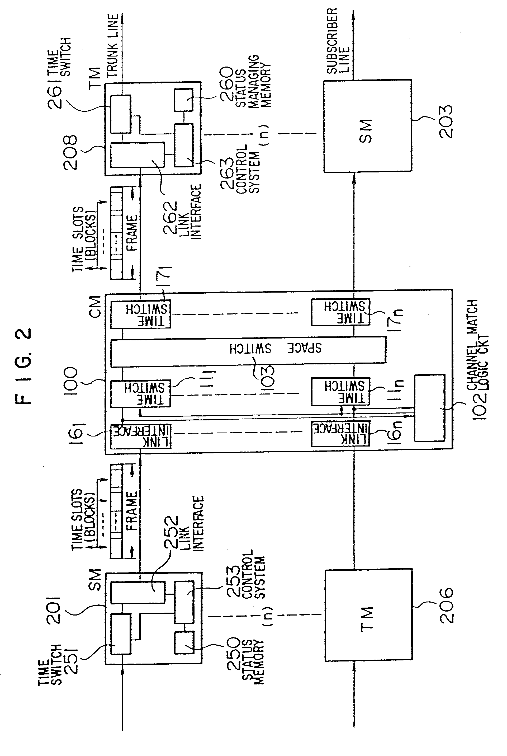
[0103] The framework of the third embodiment is such that the channel match logic circuit is operated for both the circuit switching information and packet switching information. In the case of packet switching, blocks can not all be rearranged within one frame in some instances. Therefore, in association with respective incoming FM's, buffer memories are provided for accommodating some blocks which have been invalidated for rearrangement. However, in order to process the circuit switching information with priority, a frame has a header field, whereby the number of blocks carrying the circuit switching information is communicated from respective incoming FM's to the channel match logic circuit, thereby making it possible to steadily process the blocks carrying the circuit switching information without resort to buffers.

second embodiment

[0104] In the second embodiment, since the packet buffers corresponding to respective destination FM's are provided in association with respective incoming FM's, the packet switching information can be assorted during buffering. Subsequently, the packet switching information in buffers associated with the respective incoming FM's and destined for the same destination is multiplexed by the bus circuit so as to be sent to the same destination FM.

[0105] In the third embodiment, the packet switching information is treated in the same manner as the circuit switching information. However, in contrast to the circuit switching information, the packet switching information is not assisted by the preceding acquisition of an idle circuit and in the case of the packet switching information, blocks having the same destination are sometimes concentrated. The channel match logic circuit is effectively operated for the circuit switching information to ensure that blocks destined for the same destin...


PUM


Abstract

A switching system for integratedly switching voice, data, image information and the like. The switching system comprises a plurality of front-end modules each adapted to perform a switching processing in association with a subscriber line or a trunk line, and a single or a plurality of central modules for interconnecting the plurality of front-end modules in star-type fashion and switching information prevailing between the front-end modules, in unit of block accommodating the information and a header added thereto to contain connection control information and in accordance with the contents of the header. The front-end modules are connected to the central module via inter-module highways each having frames occurring at a predetrmined period and time slots contained in each frame to carry blocks.

Description

BACKGROUND OF THE INVENTION[0001] 1 Field of the Invention[0002] This invention relates to a switching system adapted to perform switching processings of voice, data, image information and the like and more particularly to a time-division channel arrangement suitable for performing switching of information, in a unit of a block accommodating communication control information, between switching nodes or modules in a star-type configuration.[0003] 2 Description of the Related Art[0004] In the field of switching systems, studies have concentrated on the realization of high-speed and wide band performance, increase in the capacity of the channel and advanced improvements in reliability. Conceivably, a specified expedient to this end resides in the decentralization of a channel system, especially, a multiplexer stage. This expedient takes advantage of the decentralization of load which contributes to improvement in throughput increase in the capacity of the overall exchange and risk-dece...

Claims


Application Information

Patent Timeline
IPC IPC(8): H04L12/54H04L12/64H04L49/111H04Q11/04H04Q11/06
CPCH04L2012/5681H04L2012/6481H04Q11/0407H04Q11/0421H04Q11/06H04J2203/0012H04L12/56H04L12/5601H04L12/6402H04L49/101H04L49/106H04L49/15H04L49/1553H04L49/1584H04L49/205H04L49/25H04L49/254H04L49/255H04L49/256H04L49/30H04L49/3009H04L49/3018H04L49/3081H04L49/309H04L49/35H04L2012/5651H04L2012/5652
Inventor SAKURAI, YOSHITOGOHARA, SHINOBUOHTSUKI, KENICHIKATO, TAKAOKUWAHARA, HIROSHIAMADA, EIICHI
Owner HITACHI LTD
Why Eureka
Try Eureka