Network communication system with relay node for broadcasts and multicasts

a network communication system and relay node technology, applied in the field of network communication systems, can solve the problems of difficult problems, prodigious increase in network traffic, and the need for user data copying, and achieve the effect of simplifying the routing of information, automatically avoiding looped paths, and simplifying routing

Inactive Publication Date: 2002-09-12
OKI ELECTRIC IND CO LTD
View PDF3 Cites 26 Cited by
  • Summary
  • Abstract
  • Description
  • Claims
  • Application Information

AI Technical Summary

Benefits of technology

0022] Use of the relay node and star topology greatly simplifies the routing of the information, while automatically avoiding looped paths. Virtual addresses can be used to further simplify routing. Furthermore, the paths can be prearranged so as to have equal and adequate bandwidths, assuring that the information arrives at all destinations substantially simultaneously, in real time, thereby improving multicast or broadcast quality and reliability.
0023] The information sent to the destination nodes may include a time-to-live parameter, which is set to a minimum value at the relay node. This provides a simple way to ensure that the information does not propagate beyond its intended destinations.
0024] The information can be sent by wavelength division multiplexing, using the same wavelength for all destination nodes, in which case the information does not have to be copied at the relay node.

Problems solved by technology

This leads to difficult problems not encountered in unicasting.
In addition, much copying of user data is required.
(1) Complicated Routing to Avoid Looping Paths
A looped path makes it impossible for packets to reach their final destinations, not only preventing the intended communication but also causing a prodigious increase in network traffic.
There are established routing procedures for defining such loop-free paths, but while a unicast requires the routing of only a single path, a multicast or broadcast requires the definition of loop-free paths for all destinations, so inevitably the routing algorithm becomes more complicated.
The degree of congestion and other factors also vary from path to path, and it is not always possible for the necessary packets (multicast or broadcast packets) to be sent to all intended destinations.
For example, as the hop count increases, the possibility that the path may include a highly congested node increases, so the probability that multicast (or broadcast) packets may be lost due to overflow of a buffer at a highly congested node becomes higher.
(3) Poor Real-Time Performance and Simultaneity of Communications
In addition to the problem of loss of simultaneity in arrival of packets, some types of applications may have problems in maintaining real-time communication.

Method used


Image

  • Network communication system with relay node for broadcasts and multicasts
  • Network communication system with relay node for broadcasts and multicasts
  • Network communication system with relay node for broadcasts and multicasts

Examples


first embodiment

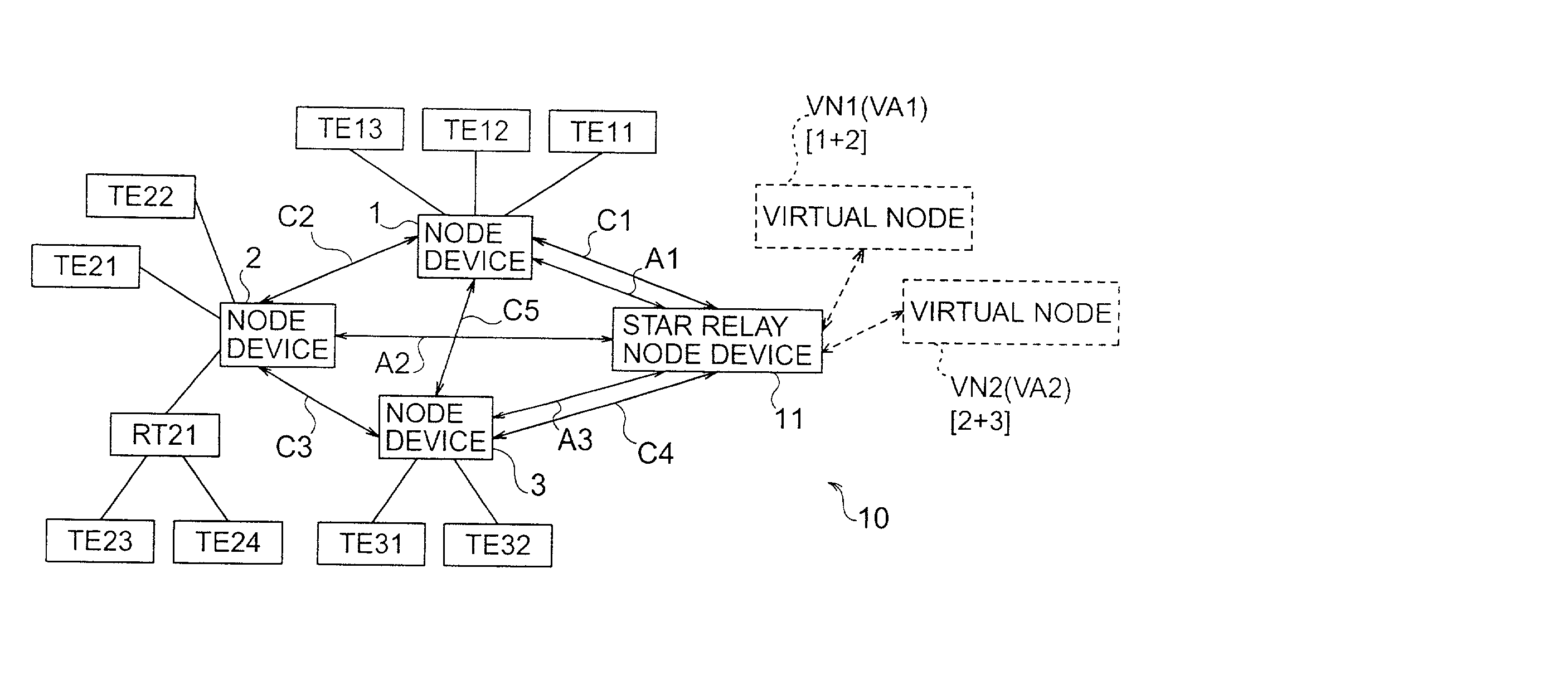
[0037] FIG. 1 shows an example of the general structure of a network communication system 10 embodying the present invention. The network communication system 10 in FIG. 1 includes node devices 1, 2, 3 and a star relay node device 11.

[0038] The node devices 1 to 3 may be terminal devices such as personal computers having networking functions, but in the present embodiment the node devices will be assumed to be routers that provide service to personal computers or other terminal equipment. Specifically, node device 1 (a router) serves terminals TE11 to TE13, node device 2 (another router) serves terminals TE21 to TE24, and node device 3 (another router) serves terminals TE31 and TE32. Terminals TE23 and TE24 are connected to node device 2 through yet another router RT21 instead of being connected to node device 2 directly. Router RT21 and terminals TE23, TE24 form a type of local area network (LAN), which may also include node device 2. Similarly, node device 1 and terminals TE11 to ...

second embodiment

[0088] The second embodiment will be described below only insofar as it differs from the first embodiment. The difference between the two embodiments is that the second embodiment uses optical communication lines and wavelength division multiplexing (WDM).

[0089] FIG. 5 shows an example of the overall structure of a network communication system 30 according to the second embodiment. The network communication system 30 comprises node devices 1A, 2A, 3A and a star relay node device 11A. Elements in FIG. 5 indicated by the same reference characters as in FIG. 1, or by similar reference characters, have corresponding functions. Specifically, the functions of virtual nodes VN1 and VN2 are the same as in FIG. 1, node devices 1A, 2A, 3A correspond to node devices 1, 2, 3 in FIG. 1, star relay node device 11A corresponds to star relay node device 11 in FIG. 1, and lines CC1, CC2, CC3, CC4, CC5 correspond to lines C1, C2, C3, C4, C5 in FIG. 1. Lines C01, C02, C03 correspond to lines A1, A2, A...

third embodiment

[0100] The third embodiment will be described below only insofar as it differs from the first embodiment. The difference is that the third embodiment dispenses with virtual nodes (and virtual addresses), and has the node device that requests a multicast perform source routing. Source routing allows the sending (source) node to designate paths under the internet protocol described in the document Request for Comments 791.

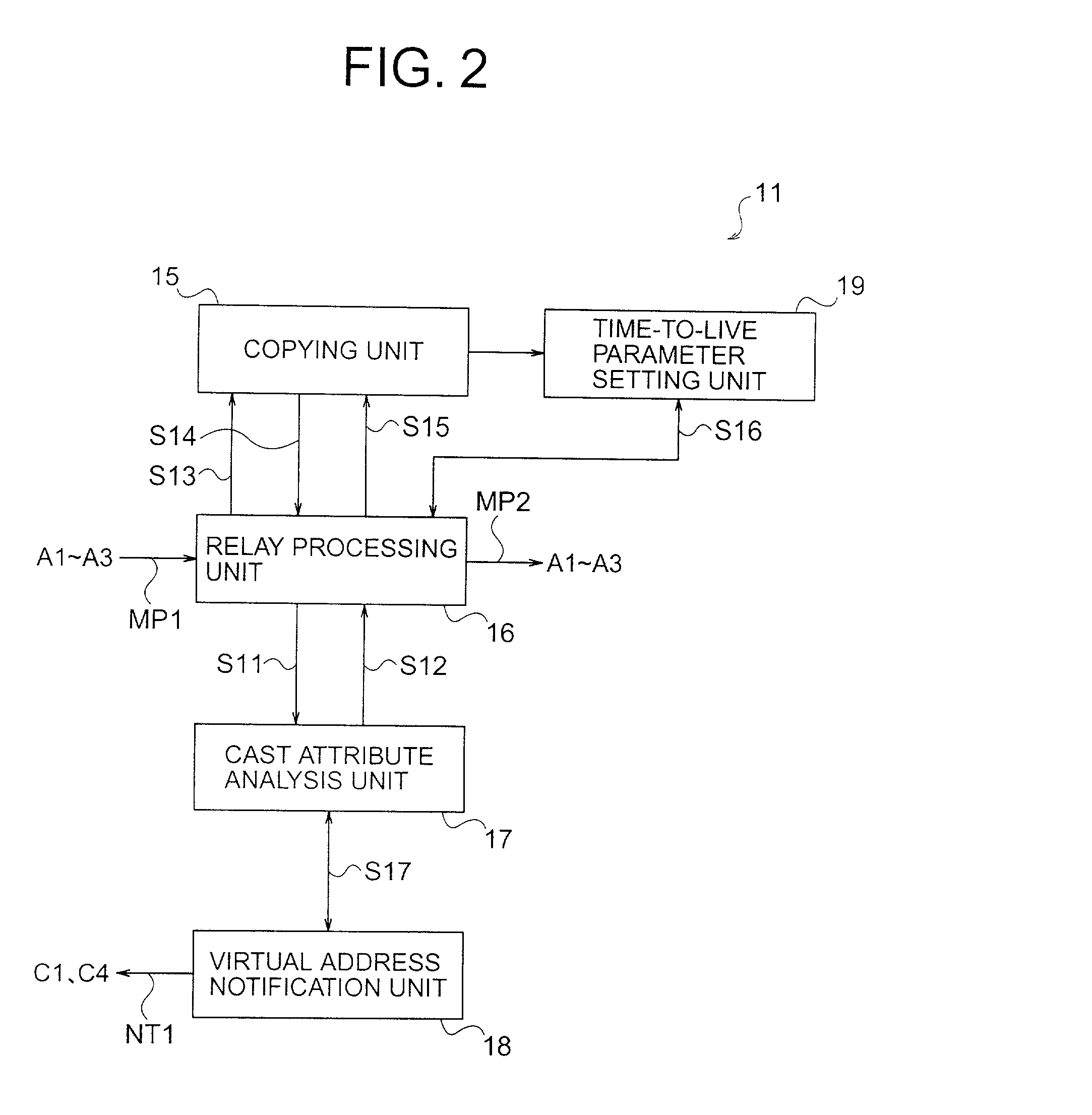
[0101] FIG. 8 shows an example of the overall structure of a network communication system 40 according to the third embodiment. FIG. 9 shows an example of the structure of the main parts of the star relay node device 11C in the third embodiment; FIG. 10 shows an example of the structure of the main parts of node devices 1C to 3C. Signals and other elements in FIGS. 9 and 10 indicated by the same reference characters as in FIGS. 2 and 3 have corresponding functions.

[0102] The node devices in the third embodiment will now be described with reference to FIG. 10. It will...


PUM


Abstract

A network communication system sends identical information from a source node to a plurality of destination nodes by first sending the information from the source node to a predetermined relay node, then sending the information from the relay node to the destination nodes over predetermined communication paths. The predetermined communication paths connect the destination nodes to the relay node in a star topology. The star topology greatly simplifies the routing of the information, while automatically avoiding looped paths, and enables the identical information to arrive at all destination nodes in real time, substantially simultaneously.

Description

BACKGROUND OF THE INVENTION[0001] 1. Field of the Invention[0002] The present invention relates to a network communication system, and more particularly to broadcasting and multicasting in a network communication system, especially one in which multiple networks are interconnected to form an internetwork or internet.[0003] 2. Description of the Related Art[0004] Internet communication has generally been one-to-one (unicast), as in electronic mail (e-mail) and the worldwide web (WWW). Recently, however, there has been a growing need to use internets for various one-to-many communication purposes, including television and radio broadcasts, teleconferencing, web data distribution, and real-time distribution of multimedia information. In this type of communication, generally referred to as multicasting or broadcasting, packets containing the same user information must be sent to a plurality of destinations simultaneously. This leads to difficult problems not encountered in unicasting.[0...

Claims


Application Information

Patent Timeline
Patent Type & Authority Applications(United States)
IPC IPC(8): H04L12/18H04L12/44H04L45/16
CPCH04L12/1836H04L12/1886H04L12/44H04L45/00H04L45/16H04L45/18H04L45/20H04L45/302H04L45/3065H04L45/62H04L45/76
Inventor YAMAUCHI, MASAKIKAJI, MAKIKO
Owner OKI ELECTRIC IND CO LTD
Why Eureka
Try Eureka