Multi-circuit, multi-injection point atomizer

a fuel injector and injection point technology, applied in the direction of machines/engines, lighting and heating apparatus, instruments, etc., can solve the problems of increasing and occupying valuable space in and around the combustion chamber, etc., to increase the fuel efficiency, increase the efficiency of the fuel injection, and increase the overall cost of the injector.

a fuel injector and injection point technology, applied in the direction of machines/engines, lighting and heating apparatus, instruments, etc., can solve the problems of increasing and occupying valuable space in and around the combustion chamber, etc., to increase the fuel efficiency, increase the efficiency of the fuel injection, and increase the overall cost of the injector.

US20020129606A1Inactive Publication Date: 2002-09-19PARKER HANNIFIN CORP

Image

  • Multi-circuit, multi-injection point atomizer
  • Multi-circuit, multi-injection point atomizer
  • Multi-circuit, multi-injection point atomizer

Examples


Embodiment Construction

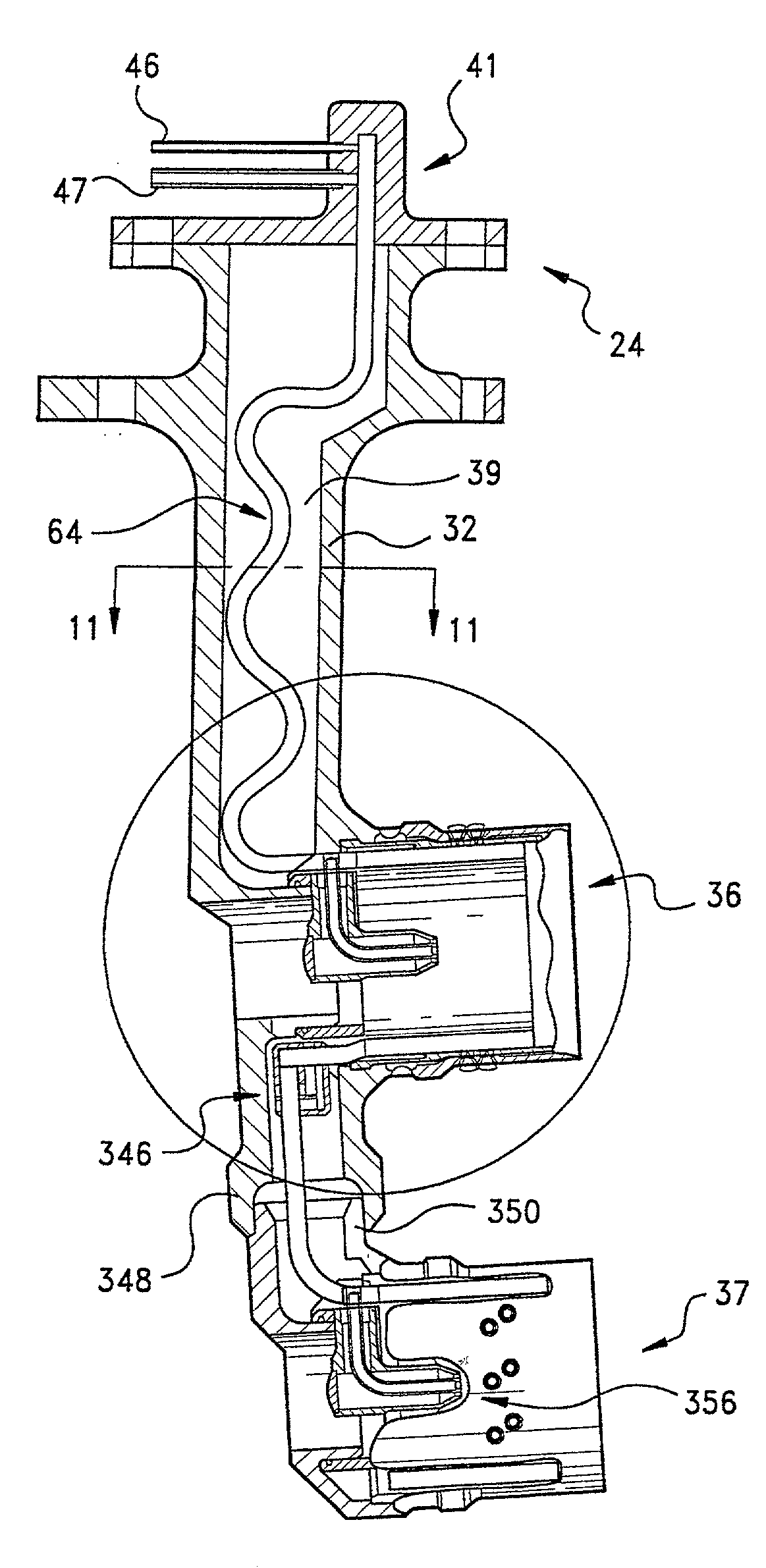
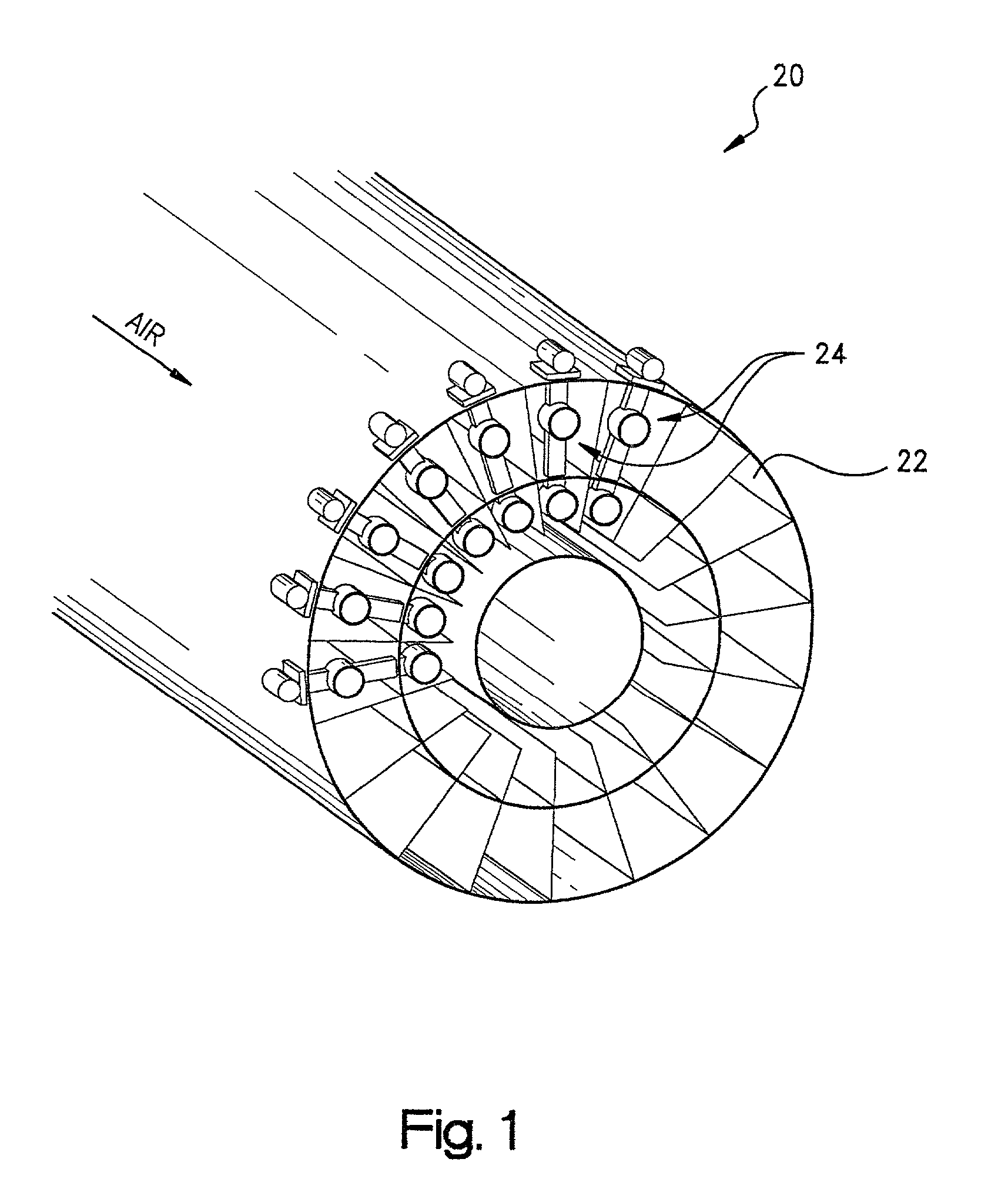
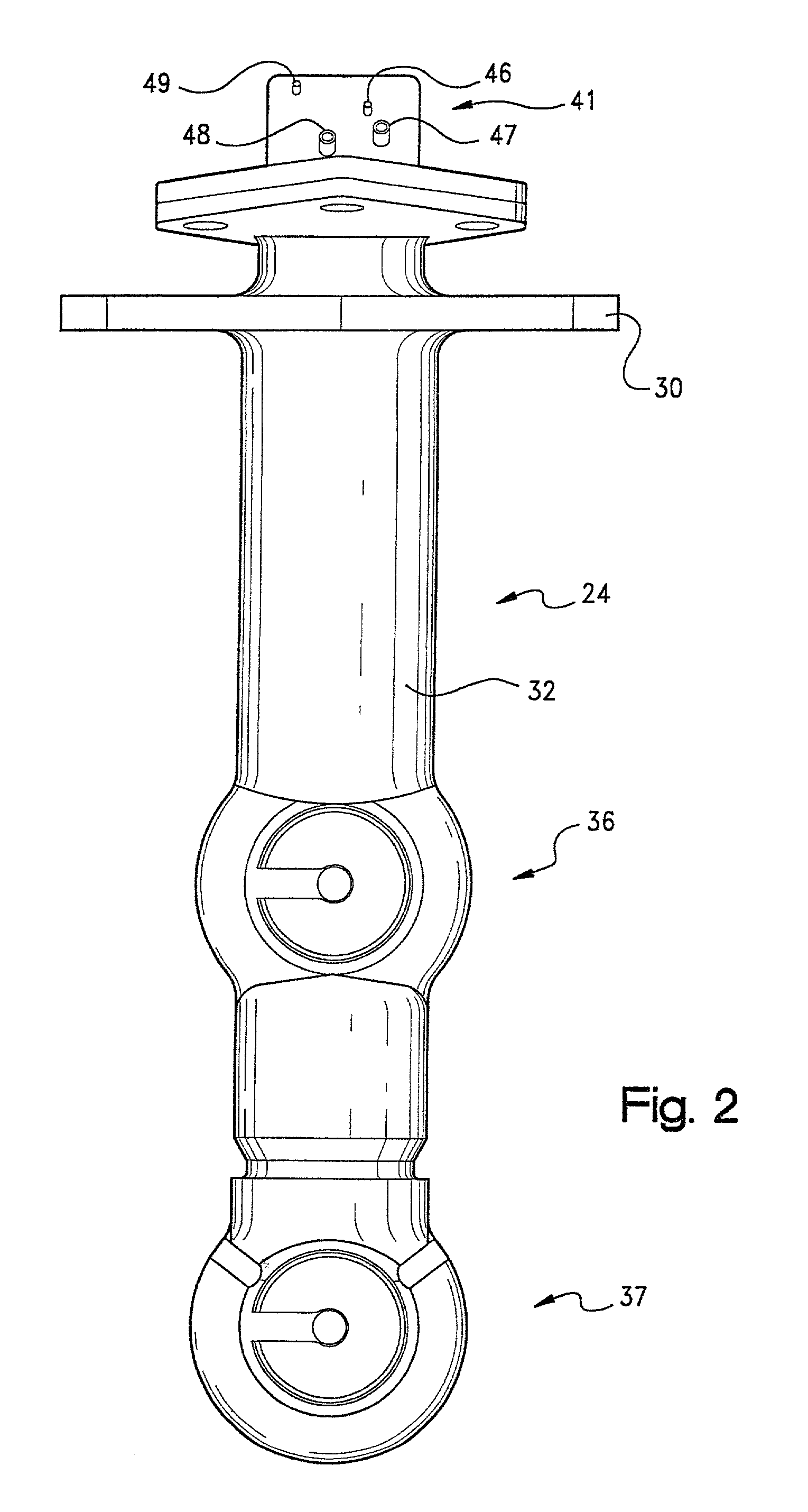
[0034] Referring to the drawings and initially to FIG. 1, a portion of a combustion engine is indicated generally at 20. The upstream, front wall of a dual combustion chamber for the engine is shown at 22, and a plurality of fuel injectors, for example as indicated generally at 24, are shown supported within the combustion chamber. The fuel injectors 24 atomize and direct fuel into the combustion chamber 22 for burning. Combustion chamber 22 can be any useful type of combustion chamber, such as a combustion chamber for a gas turbine combustion engine of an aircraft, however, the present invention is believed useful for combustion chambers for any type of combustion application. In any case, the combustion chamber will not be described herein for sake of brevity, with the exception that as should be known to those skilled in the art, air at elevated temperatures (up to 1300.degree. F. in the combustion chamber of an aircraft), is directed into the combustion chamber to allow combusti...


PUM


Abstract

A fuel injector nozzle for dispensing fuel in the combustion chamber of a gas turbine engine, includes an elongated, multi-layered, convoluted nozzle feed strip having an internal passage for directing fuel through the length of the strip from the inlet end to an outlet end; and a cylindrical, multi-layered fuel dispensing nozzle unitary with the feed strip and fluidly connected to the outlet end of the feed strip for dispensing the fuel. The multi-layered feed strip and nozzle allows complex porting of fuel circuits through the injector. The internal fluid passages through the feed strip and nozzle are formed by etching.

Description

FIELD OF THE INVENTION[0001] The present invention relates generally to fuel injectors, and more particularly, to fuel injectors useful for gas turbine combustion engines.BACKGROUND OF THE INVENTION[0002] Fuel injectors useful for such applications as gas turbine combustion engines, direct pressurized fuel from a manifold to one or more combustion chambers. Fuel injectors also function to prepare the fuel for mixing with air prior to combustion. Each injector typically has an inlet fitting connected to the manifold, a tubular extension or stem connected at one end to the fitting, and one or more spray nozzles connected to the other end of the stem for directing the fuel into the combustion chamber. A fuel passage (e.g., a tube or cylindrical passage) extends through the stem to supply the fuel from the inlet fitting to the nozpzle. Appropriate valves and / or flow dividers can be provided to direct and control the flow of fuel through the nozzle. The fuel injectors are often placed in...

Claims


Application Information

Patent Timeline
19 Sep 2002
Publication
US20020129606A1
IPC
F23R3/28; F23R3/34
CPC
F23D2211/00; F23D2213/00; F23R3/283; F23R3/34; G11C7/222
Inventors
WRUBEL, MICHAEL P.; HARVEY, REX J.