
Combustion initiation device and method for tuning a combustion initiation device

a technology of combustion initiation and combustion initiation, which is applied in the direction of insulated conductors, power cables, cables, etc., can solve the problems of affecting combustion, affecting combustion, and affecting combustion, so as to reduce harmful environmental emissions and increase engine power

Inactive Publication Date: 2002-09-19
NOLOGY ENG
View PDF0 Cites 9 Cited by
  • Summary
  • Abstract
  • Description
  • Claims
  • Application Information

AI Technical Summary

Benefits of technology

[0007] The present invention solves the problem of igniting fuel-air mixtures in the difficult conditions found in modern-day engines. Broadly, the present invention provides for complete fuel-air combustion, thereby increasing engine power and decreasing harmful environmental emissions.
[0009] Another method of the invention optimizes spark duration by coupling a resistor and a capacitor to the spark plug cable, determining an available charge from the capacitor, and selecting an ideal resistance value based on the available charge, wherein the ideal resistance value will enable the generation of a very powerful spark, thereby maximizing combustion of the fuel-air mixture.

Problems solved by technology

Combustion initiation in modern-day spark ignition engines is becoming increasingly difficult.
This is because engine designs that increase fuel economy and reduce harmful environmental emissions have created unfavorable conditions for fuel-air ignition.
Modern-day engines employ lean fuel-air mixtures that are difficult to ignite.
However, the increased engine combustion chamber pressures generated by the turbochargers and superchargers also hinder combustion.
In addition, the spacing, or gap between the spark plug's electrodes has increased, thereby increasing the amount of voltage necessary to create an ark.

Method used


Image

  • Combustion initiation device and method for tuning a combustion initiation device
  • Combustion initiation device and method for tuning a combustion initiation device
  • Combustion initiation device and method for tuning a combustion initiation device

Examples


Embodiment Construction

[0019] In the following paragraphs, the present invention will be described in detail by way of example with reference to the attached drawings.

[0020] General

[0021] Throughout this description, the preferred embodiment and examples shown should be considered as exemplars, rather than as limitations on the present invention.

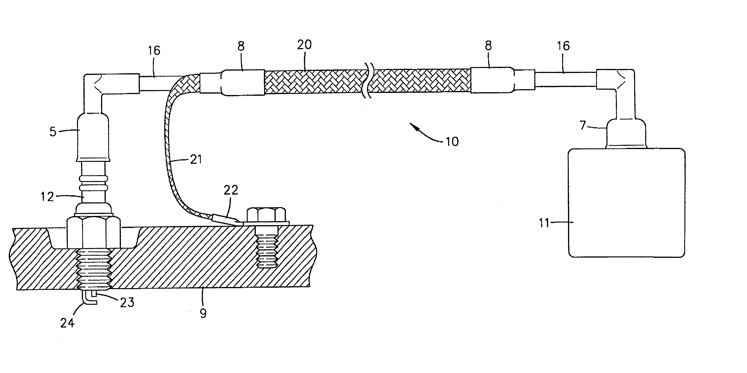
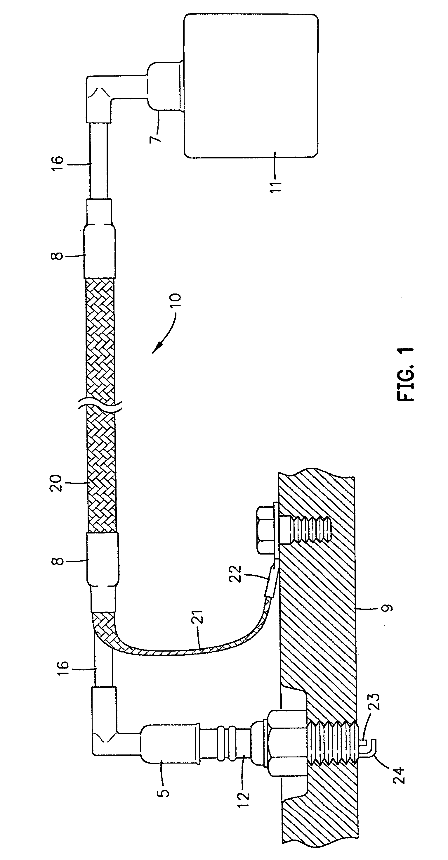
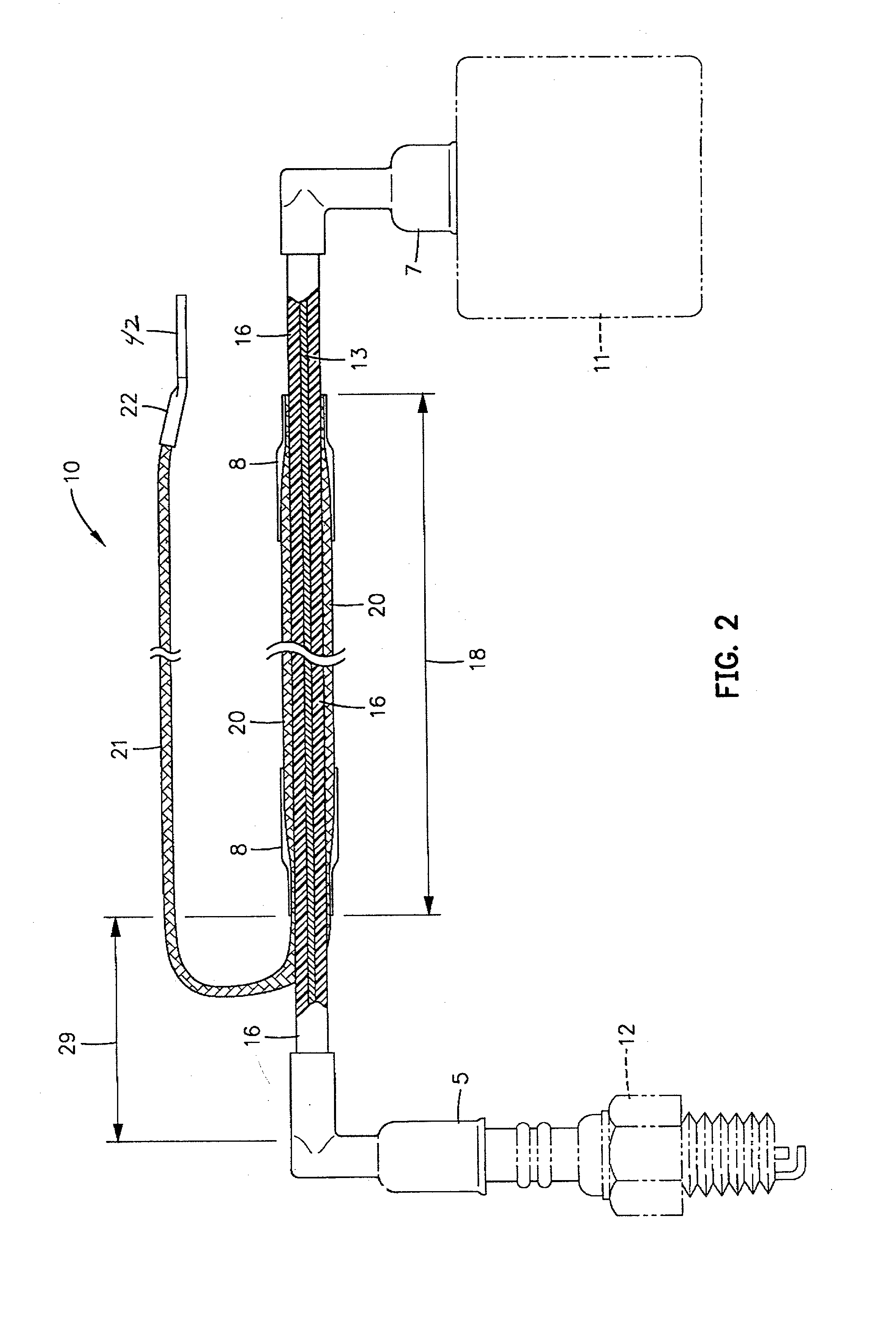
[0022] The purpose of an ignition system is to produce a powerful enough spark to initiate combustion of a fuel-air mixture. As shown in FIG. 1, an automotive ignition system comprises, in part, a spark plug 12 mounted in a cylinder head 9, a spark plug cable or ignition wire 10 and a current or power source 11 such as a coil. The spark plug cable is coupled to the spark plug by a spark plug boot 5, and to the power source by a power source boot 7. An ideal ignition system will ignite all of the fuel-air mixture and will ignite the fuel-air mixture at the precise moment to create maximum power. Therefore, the ignition system must be consistent and precise. An opti...


PUM


Abstract

An ignition cable constructed according to a method for optimizing an ignition cable, the cable comprising at least a capacitor, where the ignition cable carries current from a power source to a spark plug located in a combustion chamber. The ignition cable comprises a center element structured to communicate electric current from the power source to the spark plug and an insulator surrounding the center element. The conductor removeably coupled to a ground, and surrounds at least a portion of the insulator. The center element, insulator and conductor comprise a capacitor having an optimal capacitance value that is determined by finding a maximum capacitance value and subtracting a safety margin.

Description

REFERENCE TO RELATED APPLICATION[0001] This is a continuation-in-part of co-pending application Ser. No. 08 / 823,676, filed Mar. 24, 1997, entitled ENVIRONMENTAL SPARKPLUG-CABLE WITH COAXIAL CD-IGNITION EFFECT, based on provisional application Ser. No. 60 / 027,493, filed Sep. 30, 1996.BACKGROUND OF THE INVENTION[0002] 1. Field of the Invention[0003] The present invention generally relates to initiating combustion of fuel-air mixtures. More particularly, the invention concerns a spark plug cable and a method for tuning a spark plug cable system to maximize combustion of fuel-air mixtures in internal combustion engines.[0004] 2. Discussion of the Related Art[0005] The purpose of an ignition system is to initiate combustion of a flammable fuel-air mixture by igniting it at precisely the right moment. In spark-ignition engines, this is achieved with an electrical spark, that is, by an ark discharged between two, or more electrodes of a spark plug. An electrical potential difference, or vo...

Claims


Application Information

Patent Timeline
IPC IPC(8): F02P9/00H01T13/05
CPCF02P9/002H01T13/05
Inventor FUNK, WERNERARENS, ULF
Owner NOLOGY ENG
Learn More