Magnetic recording medium and method for manufacturing same

Inactive Publication Date: 2002-09-26
FUJI ELECTRIC CO LTD
View PDF5 Cites 42 Cited by
  • Summary
  • Abstract
  • Description
  • Claims
  • Application Information

AI Technical Summary

Benefits of technology

0068] In the lamination process of the magnetic layer components of the magnetic layer of the second magnetic recording medium of the invention, each magnetic layer component is exposed to an oxygen-containing atmosphere so as to form oxide layers on and beneath each magnetic layer component. The provision of the oxide layers more effectively supplies oxygen to the granular magnetic film to promote segregation structure. As a result, the interaction between the magnetic grains is suppressed, leading to noise reduction and Hc enhancement.
0069] Consequently, high Hc and low noise is attained even if smaller am

Problems solved by technology

As a result, the granular magnetic film that requires large amount of expensive platinum has brought about a problem of rising of manufacturing cost.
This situation is the main cause of deterioration in magnetic characteristics and electromagnetic conversion characteristics in the low Br .delta. region, Br 67 being a product of remanent magnetic flux density and film thickness.
In the future trend for the magnetic layer to become thinner, accomp

Method used


Image

  • Magnetic recording medium and method for manufacturing same
  • Magnetic recording medium and method for manufacturing same
  • Magnetic recording medium and method for manufacturing same

Examples


example 2

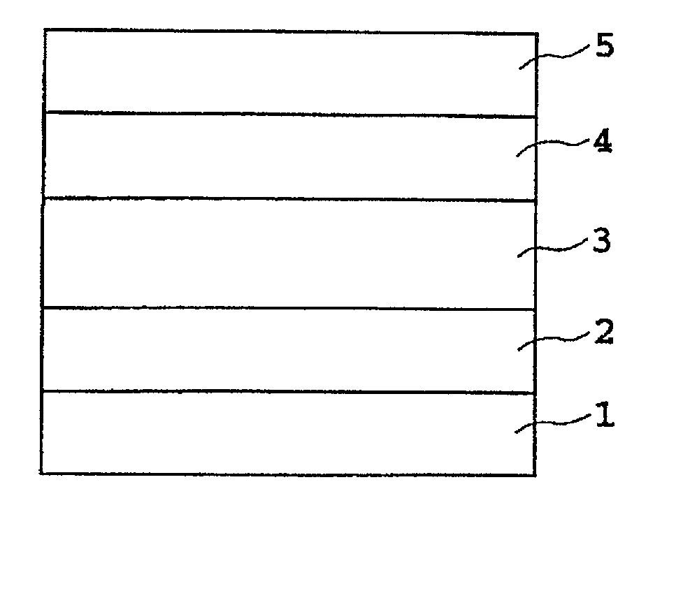
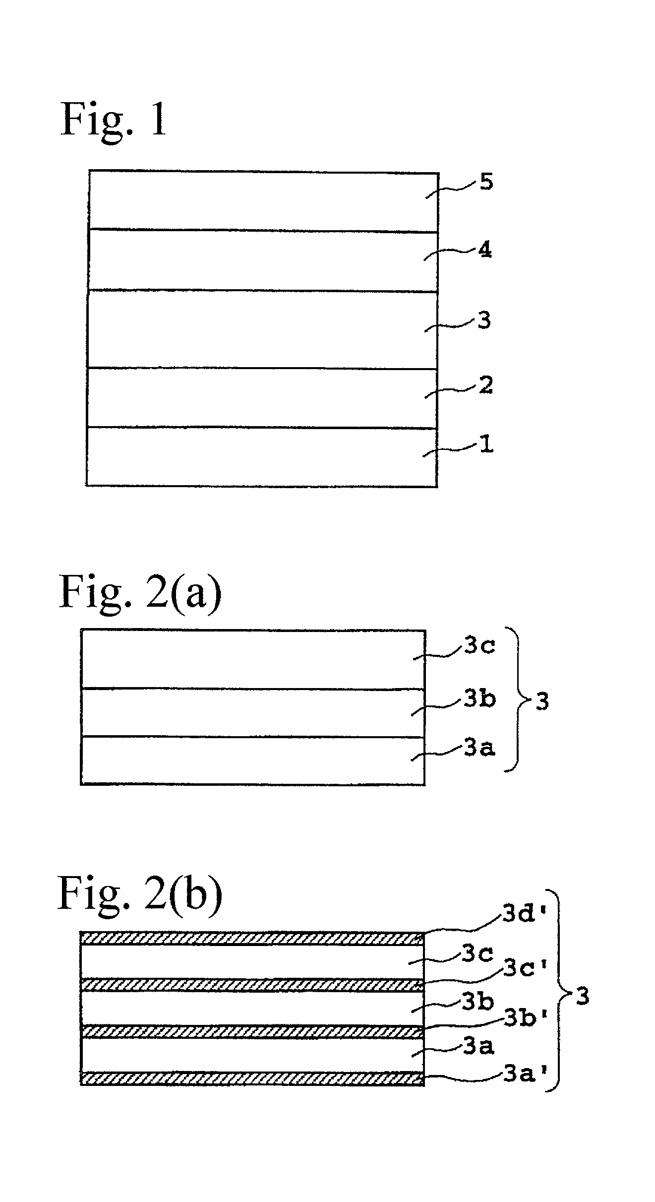
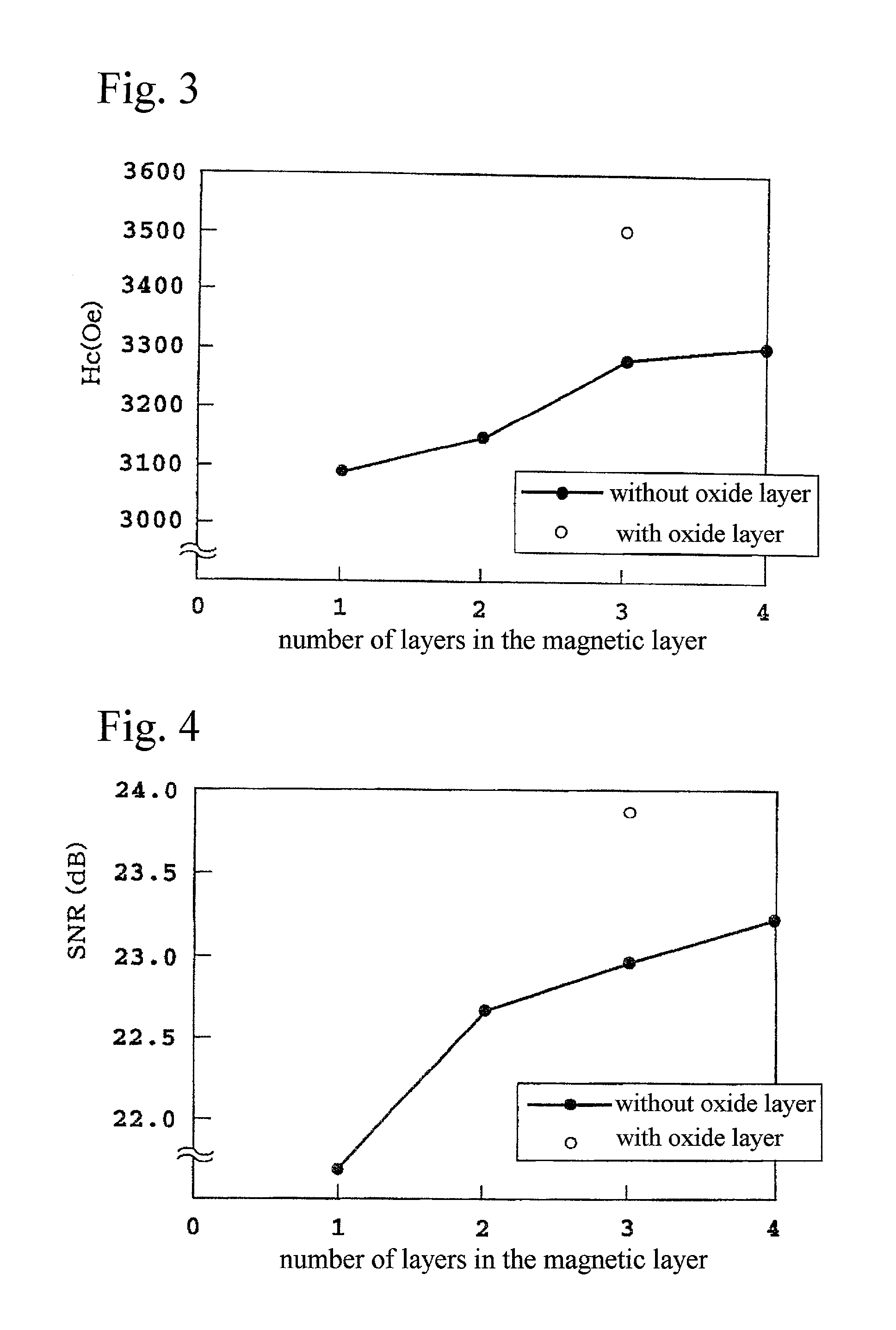
[0081] A magnetic recording medium as shown in FIG. 1 was produced in the same manner as in Example 1 except that a magnetic layer 3 shown in FIG. 2(a) having total thickness of 20 nm was provided by laminating three magnetic layer components 3a, 3b and 3c, each having thickness of about 6.7 nm.

[0082] The magnetic characteristics and electromagnetic conversion characteristics on the obtained magnetic recording medium were measured in the same manner as in Example 1.

[0083] The composition of the laminate structure of this example is shown in Table 1 and the measured characteristics are given in Table 2.

example 3

[0084] A magnetic recording medium as shown in FIG. 1 was produced in the same manner as in Example 1 except that a magnetic layer 3 having total thickness of 20 nm was provided by laminating four magnetic layer components, each having thickness of 5 mn.

[0085] The magnetic characteristics and electromagnetic conversion characteristics on the obtained magnetic recording medium were measured in the same manner as in Example 1.

[0086] The composition of the laminate structure of this example is shown in Table 1 and the measured characteristics are given in Table 2.

example 4

[0087] A magnetic recording medium as shown in FIG. 1 was produced in the same manner as in Example 2 except that a magnetic layer 3 shown in FIG. 2(b) was formed that comprises oxide layers 3a', 3b', 3c' and 3d' on and beneath each of the magnetic layer components by exposing to Ar-10% O.sub.2 gas atmosphere at 10 mTorr for 10 seconds before depositing the magnetic layer component 3a and after depositing each of the magnetic layer components 3a, 3b and 3c.

[0088] The magnetic characteristics and electromagnetic conversion characteristics on the obtained magnetic recording medium were measured in the same manner as in Example 1.

[0089] The composition of the laminate structure of this example is shown in Table 1 and the measured characteristics are given in Table 2.


PUM

PropertyMeasurementUnit
Thicknessaaaaaaaaaa
Thicknessaaaaaaaaaa
Thicknessaaaaaaaaaa

Abstract

A magnetic recording medium has a non-magnetic under-layer, a magnetic layer, a protective film and a liquid lubricant layer sequentially laminated on a non-magnetic substrate. The magnetic layer has a multi-layer structure laminated with two or more magnetic layer components, each of the magnetic layer components having ferromagnetic grains and non-magnetic grain boundaries surrounding the grain. The resulting magnetic recording medium has a granular magnetic layer exhibiting very high Hc accompanying high density of magnetic recording, while decreasing the amount of platinum needed for attaining the high Hc, and reducing media noise accompanying the high recording density.

Description

[0001] The present invention relates to a magnetic recording medium mounted on magnetic recording devices, such as an external memory device of a computer. The present invention further relates to a method for manufacturing such a recording medium.[0002] In recent years there has been a requirement for a magnetic recording medium with higher recording density and lower noise. Various conventional compositions and structures of a magnetic layer and materials for a non-magnetic under-layer and a seed layer have been proposed. In particular, a magnetic layer called the granular magnetic layer has been proposed having a structure in which a ferromagnetic grain is surrounded by non-magnetic non-metallic substance, such as oxide or nitride.[0003] Japanese Unexamined Patent Application Publication No. H8-25 5342, for example, discloses attaining low noise by forming a granular recording layer in which ferromagnetic grains are dispersed in a non-magnetic film. This is accomplished by a meth...

Claims


Application Information

Patent Timeline
IPC IPC(8): C23C14/14G11B5/65G11B5/66G11B5/673G11B5/73G11B5/738G11B5/84G11B5/851H01F10/08H01F10/16
CPCG11B5/66G11B5/84Y10T428/12611Y10T428/12861Y10T428/1259Y10T428/12868
Inventor OIKAWA, TADAAKIUWAZUMI, HIROYUKISHIMIZU, TAKAHIROTAKIZAWA, NAOKI
Owner FUJI ELECTRIC CO LTD
Why Eureka
Try Eureka