All attempts have ultimately failed because of the impracticality of wings that have to be folded out or the exposed
spinning rotor blades, propellers or jet blasts making them dangerous to pedestrians or other VTOL aircraft or flying cars.
None of this prior art contains the keys to flying car success to date.
None of the previous art illustrates a highway capable, aircraft that flies in internal, re-circulated, wind of its own making.
None of the previous art illustrates placing entire airfoils in winds of hundreds of
miles per hour for VTOL flight without a corresponding external wind that could affect pedestrians.
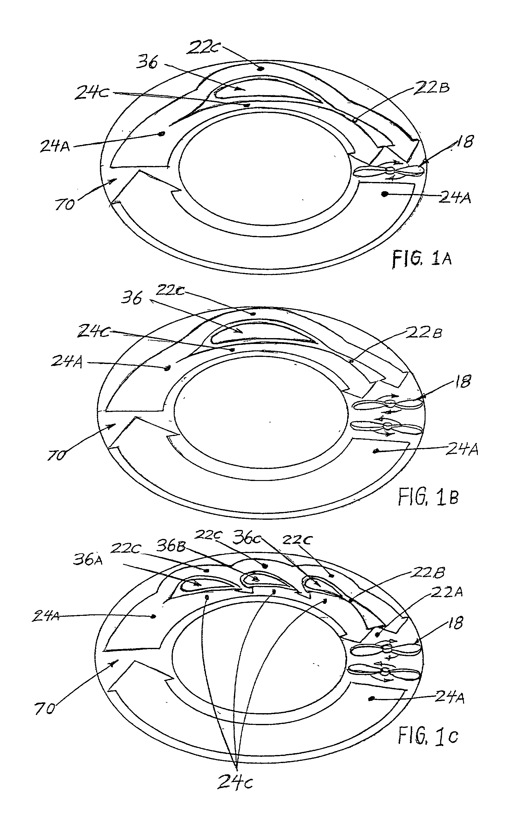
None of the previous art teaches the placement of multiple suction airfoils in series producing a lift amplification effect from one airfoil to another in a flying car.
None of the previous art teaches the use of sucked flaps within ducts on pivots for optimizing vertical or horizontal flight automatically.
None of the previous art teaches the secondary lift amplification effect of the "lift amplifying, turbulence reducing, radial, spiral
airflow generator" device.
None of the previous art illustrates a highway capable flying car with a 360-degree thruster and rotational thruster
system controlled by a single
joystick.
None of the previous art teaches a flying car boat with the capability to carry missiles,
machine guns or cannons.
None of the previous art teaches a VTOL flying car where the rotors do not lift the car, but rather, simply causes a wind for the car's fixed wings to fly in without forward movement of the car.
The drawback of blown flaps is that they produce large amounts of
aerodynamic drag and that the
airflow has a tendency to transition from a laminar to a turbulent flow, which reduces efficiency.
(a) The present invention has the additional benefit of the inherent
pendulum type stability of hanging the weight of the aircraft from the lift generating airfoils, referred to as sucked slaps, located at the highest part of the VTOL aircraft or flying car, so that any deviation from the
level flight orientation caused by winds, side accelerations and / or
thrust vectoring would be automatically countered by the equal but opposite force of gravity.
(b) An additional benefit of the internal rotor
system is the gyroscopic stability provided by the two spinning
counter rotating blade sets. The faster the blades turn, the more stable the aircraft becomes.
(c) Another benefit of the internal rotor
system is the increased efficiency of enclosed ducting around the rotor blades over the current open-air blades of today's helicopters.
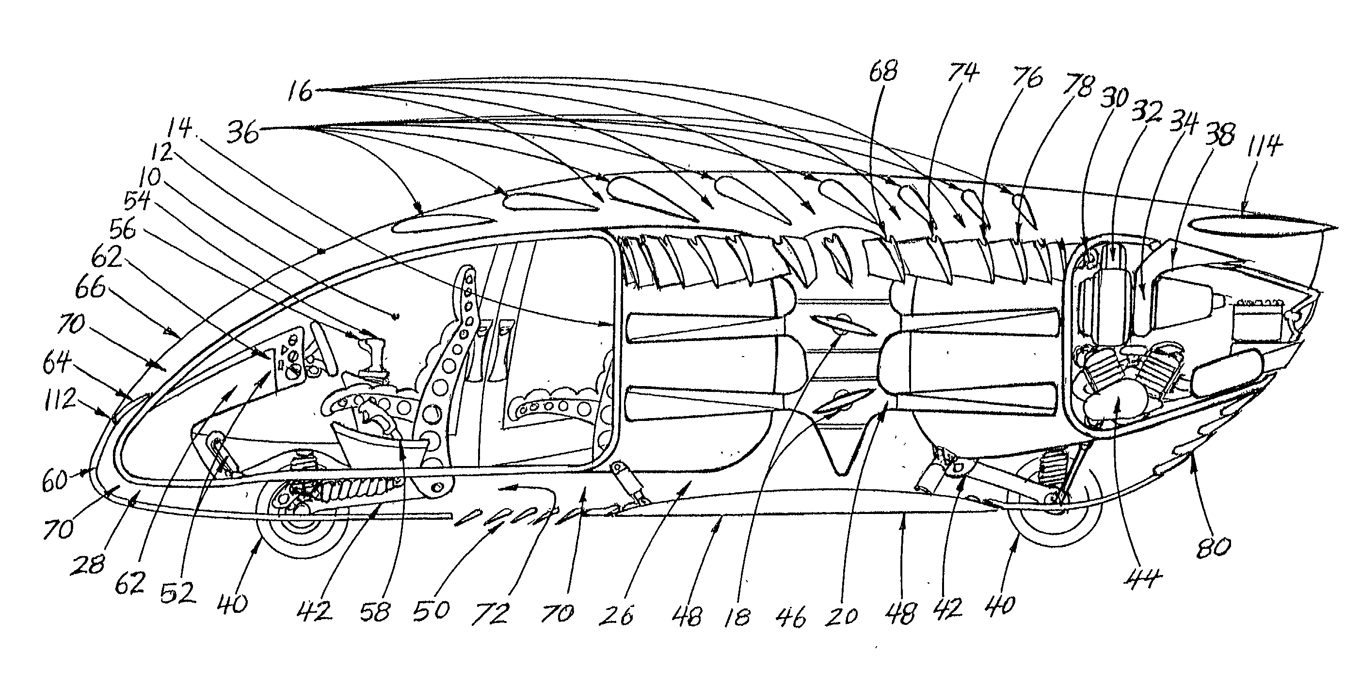
(d) Another benefit of the internal rotor system combined with the lift generating airfoils, referred to as sucked flaps, is the fact that the internal rotors never have to lift the full weight of the aircraft, like a helicopter, because the sucked flaps produce large amounts of lift at slow duct wind speeds. The sucked flaps actually lift the aircraft. The spinning rotors only provide the local internal wind in which the sucked flaps work. This takes the pressure off the ducted rotating blades and lowers the forces acting on the ducted glades relative to conventional helicopters that have to lift the entire helicopter's weight on the spinning blades.
(e) Another benefit of the internal rotor system, combined with the lift generating airfoils, referred to as sucked flaps, is the high-speed performance. Present helicopters have a problem at high speeds caused by the fact that the rotor tips of helicopters move forward on one side and rearward on the other side of the helicopter relative to the
forward speed of the helicopter. When the
forward speed of the helicopter is added to the rotor tip speed on the advancing side of the helicopter, the rotor tip reaches the
speed of sound on one side and not on the other, this causes
instability and a highly dangerous flight condition. With the internal rotor system combined with the sucked flaps, the internal rotors are protected form the
wind speed of the forward motion of the aircraft allowing the VTOL aircraft or flying car to fly very close to the
speed of sound without the problems inherent with present helicopters. In fact, because the
forward speed of the aircraft increases the left generated by the sucked flaps lift generated airfoils, the need for higher
rotor speed actually goes down as the forward speed of the aircraft provides lift with less help from the rotors.
(f) Another benefit of the present invention is the
slow speed to high-speed transition of the present invention from
high lift to high speed. This is an example of the dual efficiency of this system. At
slow speed, the present invention causes a rush of
atmosphere at hundreds of
miles per hour to be blown and drawn across the sucked flaps causing an estimated 144 tons of lift at 200
miles per hour to lift the approximately 2
ton flying car or aircraft with great
vertical acceleration. Much slower wind speeds of approximately 35 miles per hour will result in an estimated 2.5 tons of lift causing the 2
ton flying car or aircraft to gently rise above a crowded street with minimal wind affecting pedestrians or other VTOL aircraft or flying cars. Once the flying car or aircraft has risen high above the pedestrians and other VTOL aircraft or flying cars below, the internal
wind speed can be increased to produce an improved rate of
climb to rise above buildings. Once above the physical obstructions of the city, the laminar 360-degree
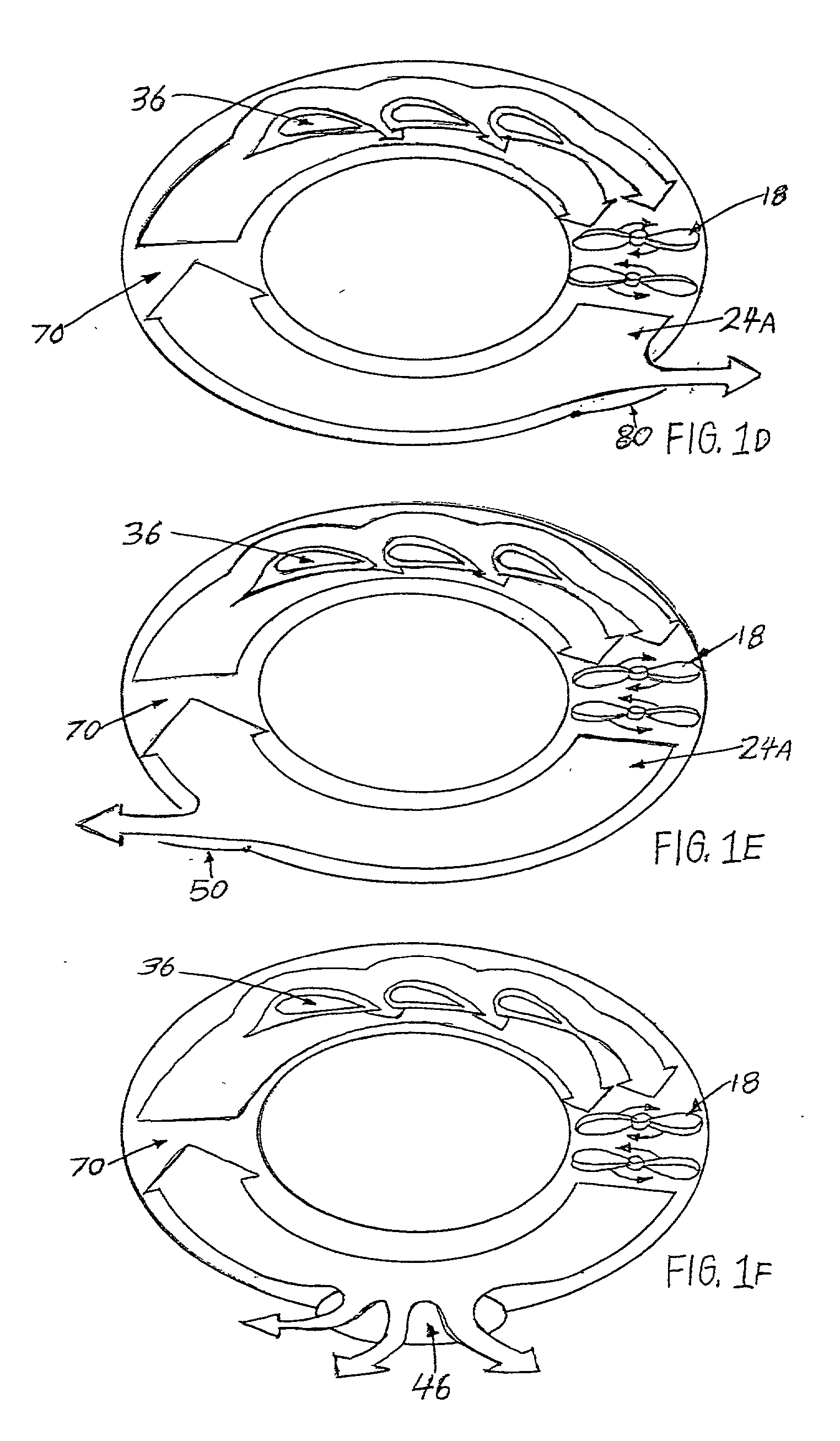
thrust vectoring nozzle at the base of the duct controls the direction and speed of the flying car or aircraft. As the laminar 360-degree
thrust vectoring nozzle is controlled to cause the internal wind to be directionally forced to the rear of the flying car or aircraft; the VTOL aircraft or flying car starts to accelerate in a forward direction. The laminar 360-degree thrust vectoring
nozzle at the base of the duct also controls the direction of flight, the angular attitude of the flying car or aircraft, and the banking of the flying car or aircraft to balance the centrifugal and
gravitational force directly under the VTOL aircraft or flying car for passenger comfort during high speed turns. As the flying car or aircraft accelerates forward, the sucked flaps are exposed to the oncoming atmosphere in the form of a high-speed wind rushing over their lift generating surfaces causing speed-induced lift. This speed-induced lift reduces the need for the internal rotors to provide
airspeed over the lift generating surfaces. Under this high-speed condition, the rotor
pitch can be moved toward the feathered position and the rotor rotational speed can be reduced for energy savings while traveling toward the destination. When the destination is reached, the laminar 360-degree thrust vectoring nozzle is controlled to cause the internal wind to be directionally forced to the front of the flying car or aircraft and the VTOL aircraft or flying car starts to decelerate. As the flying car or aircraft decelerates, the speed-induced lift starts to fade and the internal rotors are moved from a feathered to an active wind generated
pitch and the rotational speed of the internal rotors is increased to transformed speed into lift for landing or
slow speed movement between tall objects. In a situation where the flying car or aircraft is traveling at a
high rate of speed, on a freeway for example, the amount of power required to
takeoff would be reduced by the amount of forward speed involved. In a situation where the flying car or aircraft is traveling through the atmosphere and descends onto a freeway for example, the amount of power required for landing would be reduced by the amount of forward speed involved.

