
Methods for making molecular sieves

Inactive Publication Date: 2002-10-10
CHEVROU USA INC
View PDF0 Cites 19 Cited by
  • Summary
  • Abstract
  • Description
  • Claims
  • Application Information

AI Technical Summary

Benefits of technology

[0025] Another object is to provide such a method which uses a low water volume while achieving a highly uniform and rapid distribution of heat to a reaction mixture, without breakage or clumping of shaped particles.
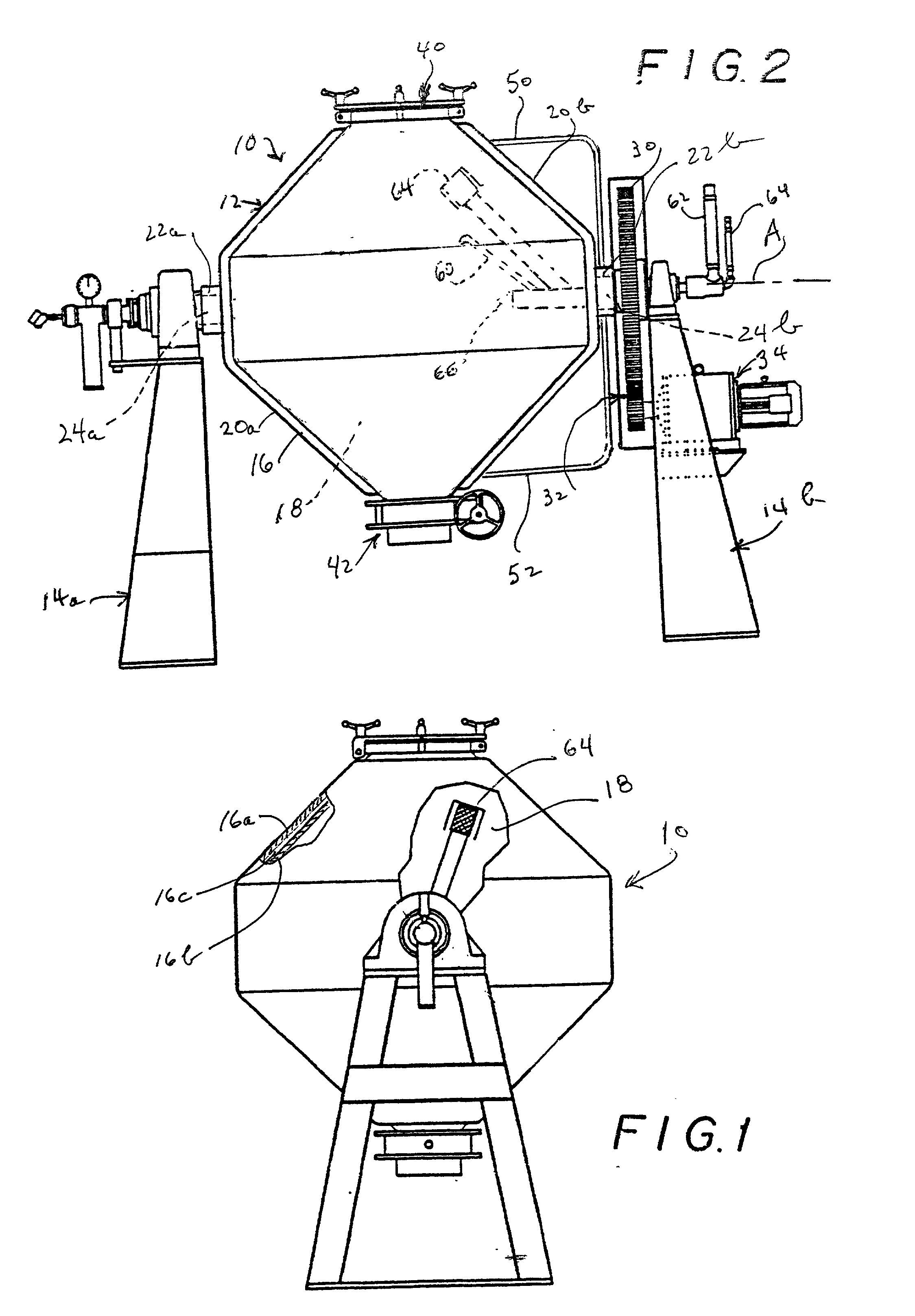
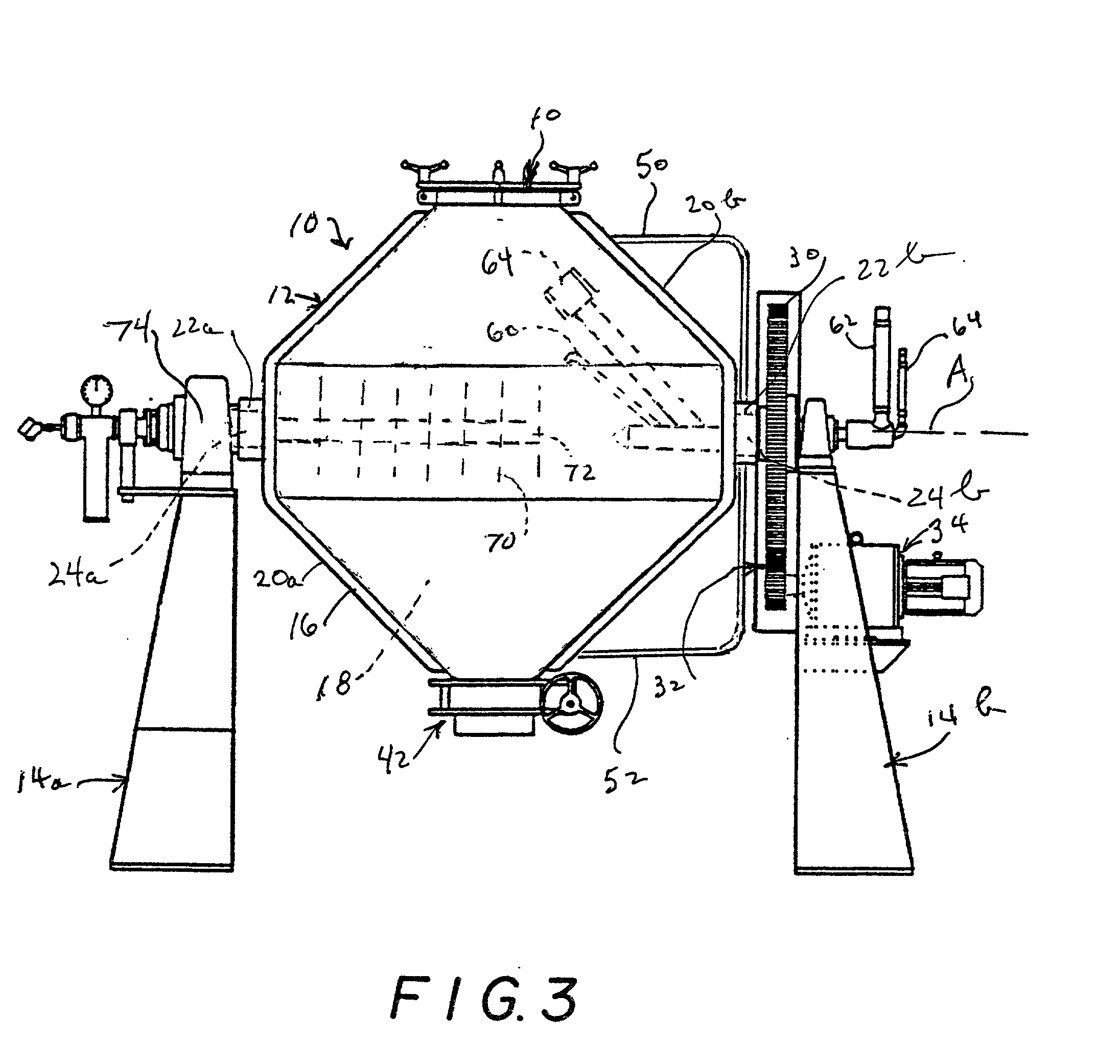
[0028] A method has been discovered which surprisingly enables an inextrudate reaction mixture to be effectively crystallized to produce zeolitic or non-zeolitic molecular sieves. The reaction mixture is heated within a slowly rotating, double-walled reactor vessel wherein a heated medium is conducted within a space formed between the double walls of the vessel. Thus, the reaction mixture is contacted by a uniformly heated wall while being gently tumbled at low speed. The tumbling action serves to uniformly distribute the heat within the reaction mixture without subjecting the mixture to such shearing that could damage shaped particles. A relatively high quantity of reaction mixture can be handled in that way to maximize the production volumes and reduce production costs.

Problems solved by technology

Also, the separated water may have to be treated for environmental reasons.
Due to the relatively low quantity of water in the reaction mixture used in the low-extrudate methods of making zeolite or non-zeolite molecular sieves, it is not possible to use a conventional mechanical stirrer since the stirrer would encounter too much resistance in the high-solids mixture (in contrast to the low resistance encountered in the low-solids mixture used in the conventional methods).
On the other hand, in the absence of a thorough mixing of the reaction mixture during the heating phase, the reaction mixture will not be uniformly heated; and if formed particles are present in the reaction mixture, clumping of those particles could occur.
Those problems might be alleviated by using a smaller quantity of reaction mixture in the reactor, but then the rate of production would be undesirably reduced.

Method used


Image

  • Methods for making molecular sieves
  • Methods for making molecular sieves

Examples


example 1

[0081] 1800 grams of silica (HiSil 233, a hydrated silica manufactured by PPG) were placed in a Baker-Perkins mixer. To this were added 78 grams of NaAlO.sub.2 with mixing. Then 1344 grams of a 35% aqueous solution of tetraethylammonium hydroxide (TEAOH) and 144 grams of a 50% aqueous solution of NaOH were added with mixing. Then were added 187.2 grams of acid-peptized and neutralized Versal 250 alumina (45 wt % Al2O3, 55 wt % H2O) followed by 84 grams of kaolin clay and 18 grams Beta zeolite. To this was added 1035 grams of deionized water and mixed at 140.degree. F. until the mix went to a paste. The mix was then heated to 160.degree. F. with slow mixing until it reached an extrudable form (volatiles level of 55% by LOI). The mix was extruded through a {fraction (1 / 16)}-inch die using a Ram extruder, and placed on a screen to dry at room temperature to a volatiles content of 45 wt %. Molar ratios in the extrudate were as follows:

[0082] R.sup.+ / SiO2=0.12

[0083] OH.sup.- / SiO2=0.18

[00...

example 2

[0088] 12,000 grams of HiSil 233 were placed in a Littleford mixer. To this were added 240 grams of NaAlO.sub.2 and 120 grams of kaolin clay, and mixed for 15 minutes. Next were added 12,000 grams of a 35% aqueous solution of TEAOH, followed by 640 grams of a 50% aqueous solution of NaOH, then 240 grams of NaNO.sub.3 and 40 grams of Na.sub.2B.sub.2O.sub.4.8H.sub.2O, and mixed for three hours. Then 20 grams of Beta zeolite were added and mixed for another 15 minutes. Steam heat, at 160.degree. F., was applied to the mixer jacket to reduce volatiles level in the mix to 51.5 wt %. The mix was then dumped out of the mixer and loaded into the Abbe crystallizer. Molar ratios in the mix were as follows:

[0089] R.sup.+ / SiO2=0.16

[0090] OH.sup.- / SiO2=0.20

[0091] M.sup.+ / SiO2=0.08

[0092] SiO2 / Al2O3=94

[0093] H2O / SiO2=2.5

[0094] The mix was crystallized for 48 hours at 280.degree. F. (oil inlet temperature of 300.degree. F.) with a rotation speed of 10 rpm. At the conclusion of the run, the unit was...

example 3

[0095] 6000 grams of HiSil WB-15D silica were placed in a Littleford mixer. To this were added 1500 grams of 98% tetrapropylammonium bromide (TPA-Br) and mixed for 15 minutes. Next were added 3000 grams of a 35% aqueous solution of TEAOH and mixed for three hours. The mix was then dumped out of the mixer and loaded into the Abbe crystallizer. Molar ratios in the mix were as follows:

[0096] R.sup.+ / SiO2=0.14

[0097] OH.sup.- / SiO2=0.08

[0098] H2O / SiO2=3.2

[0099] The mix was crystallized for 20 hours at 280.degree. F. with a rotation speed of 10 rpm. At the conclusion of the run, the unit was cooled to room temperature and the catalyst was dumped through the ball valve. The catalyst was then washed three times with a three-fold excess of a 10% ammonium nitrate solution containing 6 grams of nitric acid per 1000 grams of solution. The catalyst was then dried in a vacuum oven overnight at 120.degree. C., then calcined in air at 1100.degree. F. for six hours. X-ray diffraction analysis showed ...


PUM


Abstract

An in-extrudate reaction mixture to be effectively crystallized is effectively crystallized to produce zeolitic or non-zeolitic molecular sieves. The reaction mixture is heated within a slowly rotating, double-walled reactor vessel wherein a heated medium is conducted within a space formed between the double walls of the vessel. Thus, the reaction mixture is contacted by a uniformly heated wall while being gently tumbled at low speed. The tumbling action serves to uniformly distribute the heat within the reaction mixture without subjecting the mixture to such shearing that could damage shaped particles. A relatively high quantity of reaction mixture can be handled in that way to maximize the production volumes and reduce production costs.

Description

[0001] The present invention relates to a method for producing molecular sieves.[0002] Molecular sieves are a commercially important class of crystalline materials. They have distinct crystal structures with ordered pore structures which are demonstrated by distinct X-ray diffraction patterns. The crystal structure defines cavities and pores which are characteristic of the different species. Natural and synthetic crystalline molecular sieves are useful as catalysts and adsorbents. The adsorptive and catalytic properties of each molecular sieve are determined in part by the dimensions of its pores and cavities. Thus, the utility of a particular molecular sieve in a particular application depends at least partly on its crystal structure. Because of their unique sieving characteristics, as well as their catalytic properties, molecular sieves are especially useful in such applications as gas drying and separation and hydrocarbon conversion. The term "molecular sieve" as used herein refe...

Claims


Application Information

Patent Timeline
IPC IPC(8): B01F9/00B01F15/06B01J8/10B01J19/00B01J29/06B01J29/08B01J29/40B01J29/70B01J29/83C01B37/00C01B39/02C01B39/24C01B39/32C01B39/38
CPCB01F9/0005Y10S423/30B01F2009/0072B01F2015/062B01J8/10B01J29/06B01J29/084B01J29/40B01J29/7007B01J29/83B01J2219/00094B01J2219/182B01J2219/1947C01B37/00C01B39/02C01B39/24C01B39/32C01B39/38Y10S423/22Y10S423/21Y10S423/28B01F15/065B01F29/20B01F29/40353B01F2035/99B01F35/92
Inventor MILLER, STEPHEN JOSEPHCHERNEY, SEYMOUR
Owner CHEVROU USA INC
Learn More