
Biosensor

a biosensor and sensor technology, applied in the field of biosensors, can solve problems such as filter deformation

Inactive Publication Date: 2002-10-17
PANASONIC HEALTHCARE HLDG CO LTD
View PDF6 Cites 35 Cited by
  • Summary
  • Abstract
  • Description
  • Claims
  • Application Information

AI Technical Summary

Benefits of technology

0029] It is desirable that part or all of the cover member and the insulating base plate are transparent.

Problems solved by technology

The width over 5.0 mm may undesirably lead to deformation of the filter under vibrations applied to the sensor.

Method used


Image

  • Biosensor
  • Biosensor
  • Biosensor

Examples


example 1

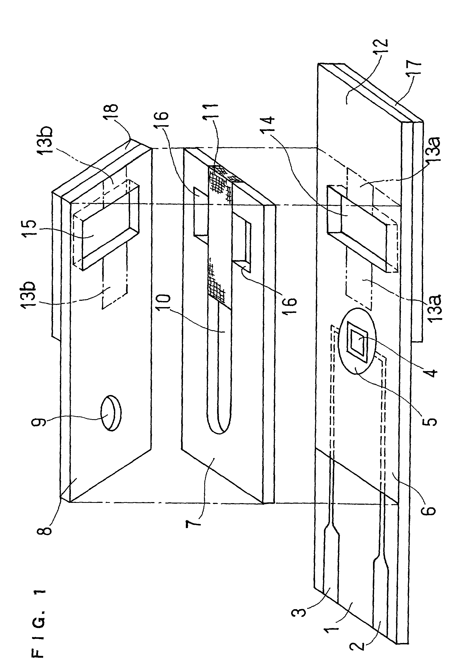
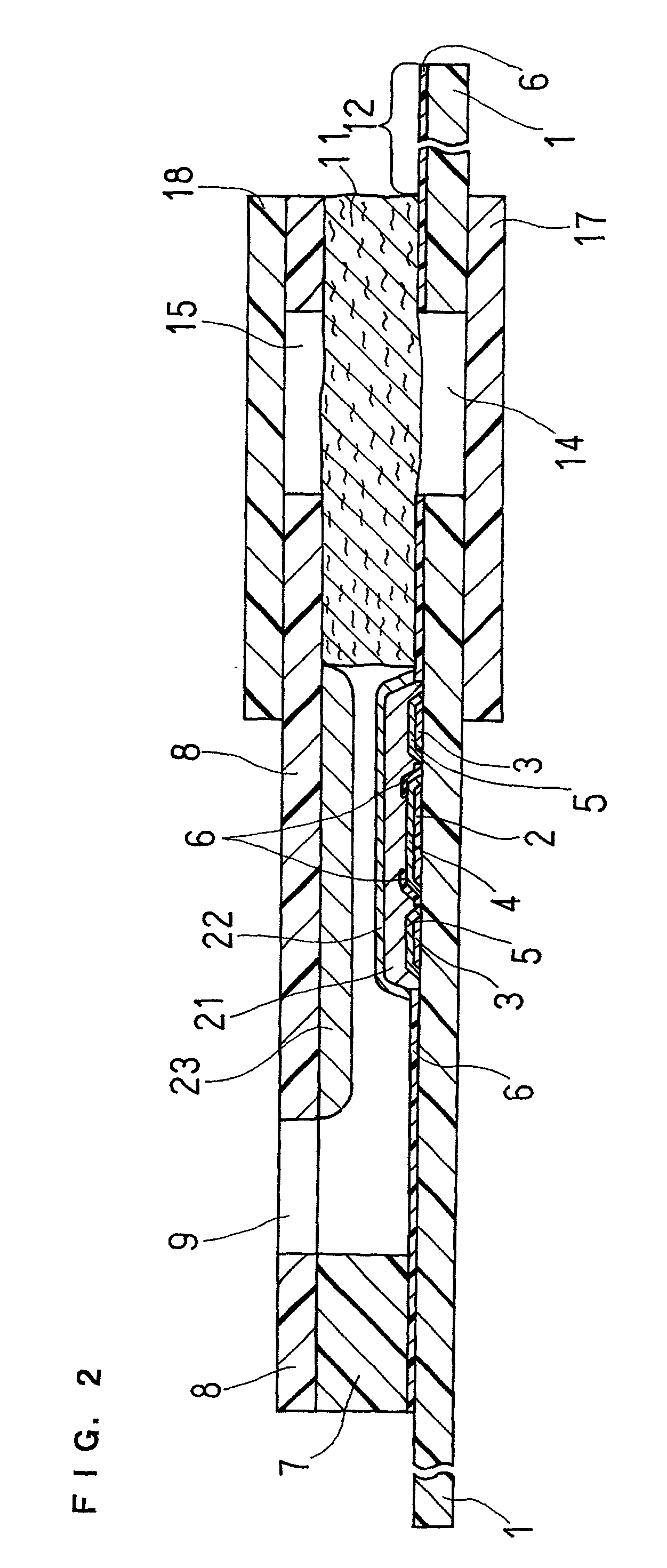
[0072] A cholesterol sensor was produced as an example of the biosensors. The process first added a 0.5% by weight of aqueous solution of sodium carboxymethyl cellulose (hereinafter referred to as CMC) as the hydrophilic polymer dropwise onto the electrode system on the insulating base plate 1 shown in FIG. 1 and dried the solution in a hot blast drier at 50.degree. C. for 10 minutes, so as to form a CMC layer 21. The process subsequently added 4 .mu.l of an aqueous solution of potassium ferricyanide (corresponding to 70 mM potassium ferricyanide) as the electron mediator dropwise on to the CMC layer and dried the solution in the hot blast drier at 50.degree. C. for 10 minutes, so as to form a potassium ferrocyanide layer 22.

[0073] The process then added 2 .mu.l of a 2% by weight of ethanol solution of Triton X-100 as the surface active agent dropwise into a recess defined by the cover 8 and the slit 10 of the spacer 7, and dried the solution at room temperature for 3 minutes, so as...

example 2

[0077] In Example 1, the reaction reagent system was composed of the enzyme / surface active agent layer 23 formed by the freeze drying method on the rear face of the cover in the sample solution supply pathway and the CMC layer 21 and the potassium ferricyanide layer 22 formed by the air drying method at the specified position covering over the electrode system on the base plate. In this example, as shown in FIG. 4, the reaction reagent system was composed of a porous carrier 24, which was in contact with an end of the filter 11 and had enzymes, a surface active agent, and an electron mediator soaked therein and carried thereon, and the CMC layer 21 formed by the air drying method at the specified position covering over the electrode system on the base plate.

[0078] The arrangement of making part of the reagents included in the reaction reagent system carried on the porous carrier enhances the solubility of the reaction reagents into the sample solution, as in the case of the freeze d...


PUM

PropertyMeasurementUnit
widthaaaaaaaaaa
widthaaaaaaaaaa
thicknessaaaaaaaaaa

Abstract

The present invention provides a biosensor that enables highly-accurate measurement of a sample solution including a solid component like hemocytes and has a little variation in response. The biosensor includes: an insulating base plate, an electrode system having at least a working electrode and a counter electrode provided on the base plate, a cover member that is combined with the base plate to define a sample solution supply pathway for leading a sample solution from a sample supply unit to the electrode system, a reaction reagent system including at least an oxidation-reduction enzyme and an electron mediator, and a filter disposed between the electrode system and the sample supply unit in the sample solution supply pathway. The biosensor has a space that encircles surface of the filter in an area from one end of the filter close to the sample supply unit to the other end of the filter close to the electrode system. This arrangement effectively prevents the solid component like hemocytes from flowing into the electrode system without being filtered out by the filter.

Description

[0001] The present invention relates to a biosensor that carries out high-speed, highly-accurate, simple determination of a target object in a sample.[0002] A biosensor has been proposed to determine a specific component in a sample by a simple procedure without any dilution or stirring the sample solution (Japanese Laid-Open Patent Publication No. 2-062952).[0003] In this biosensor, an electrode system including a measurement electrode or a working electrode, a counter electrode, and a reference electrode is formed on an insulating base plate, for example, by screen printing. An enzyme reaction layer including a hydrophilic polymer, an oxidation-reduction enzyme, and an electron mediator is then formed on the electrode system. A buffer may be added to this enzyme reaction layer according to the requirements.[0004] When a sample solution containing a substrate is added dropwise onto the enzyme reaction layer in the biosensor thus constructed, the enzyme reaction layer is dissolved t...

Claims


Application Information

Patent Timeline
Patent Type & Authority Applications(United States)
IPC IPC(8): C12Q1/00G01N33/487G01N33/49
CPCG01N27/3272C12Q1/004
Inventor YAMAMOTO, TOMOHIROHASEGAWA, MIWAWATANABE, MOTOKAZUIKEDA, SHINNANKAI, SHIRO
Owner PANASONIC HEALTHCARE HLDG CO LTD
Learn More