
Directed least recently used cache replacement method

a cache memory and cache technology, applied in the direction of memory adressing/allocation/relocation, instruments, climate sustainability, etc., can solve the problems of limited storage capacity, inability to fully implement such prediction arrangements, and general limiting factors of the overall performance of the processor

Inactive Publication Date: 2002-10-17
IBM CORP
View PDF0 Cites 45 Cited by
  • Summary
  • Abstract
  • Description
  • Claims
  • Application Information

AI Technical Summary

Benefits of technology

[0012] It is another object of the invention to provide for maximizing processor performance for particular application programs by improving cache hit rates selectively for individual applications in a processor and cache hardware independent manner.

Problems solved by technology

The data and instructions must be provided from some form of memory and the access time to either or both is generally a limiting factor in the overall performance of the processor.
Similarly, but for different reasons, the access cycle times of dynamic memories which may be included on the same chip with the microprocessor (but may be particularly limited in storage capacity by the amount of available chip space) will be much shorter than a similarly designed memory structure of larger capacity on a different chip because of the difference of signal path length and propagation time.
However, no such prediction arrangement can be fully effective and the performance of a processor is often considered to be limited by the cache miss rate or the relative number of times needed data or instructions are not available from the cache or top level of a cache hierarchy when called by the processor and when a longer access cycle time must be used to access the data or instructions from a different level of cache or from mass memory.
Further, such algorithms must be supplemented by other algorithms which remove data from the cache since it is reasonable to assume that the probability of a line of data or instructions (already placed in a cache) being needed may diminish over time.
However, at the present state of the art, further gains are difficult even when adaptive techniques are employed which may consume significant amounts of processor power.

Method used


Image

  • Directed least recently used cache replacement method
  • Directed least recently used cache replacement method
  • Directed least recently used cache replacement method

Examples


Embodiment Construction

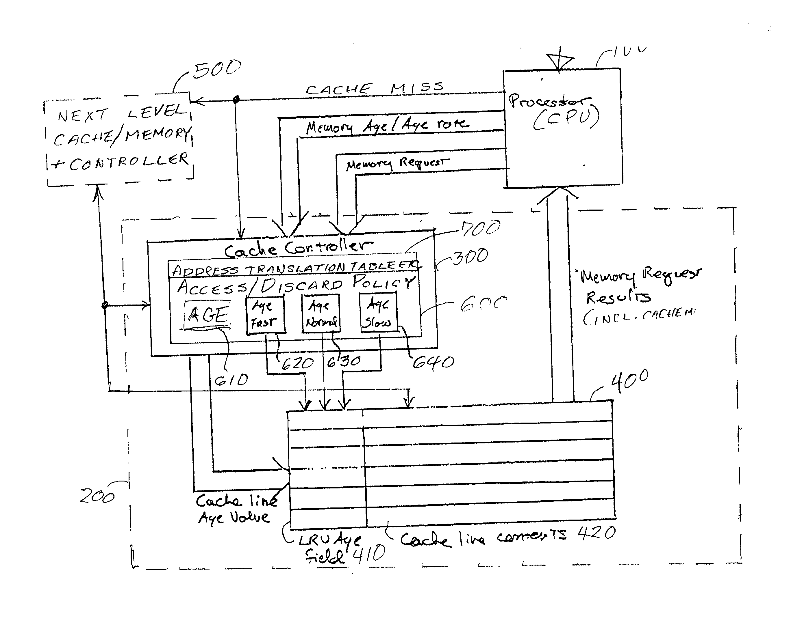
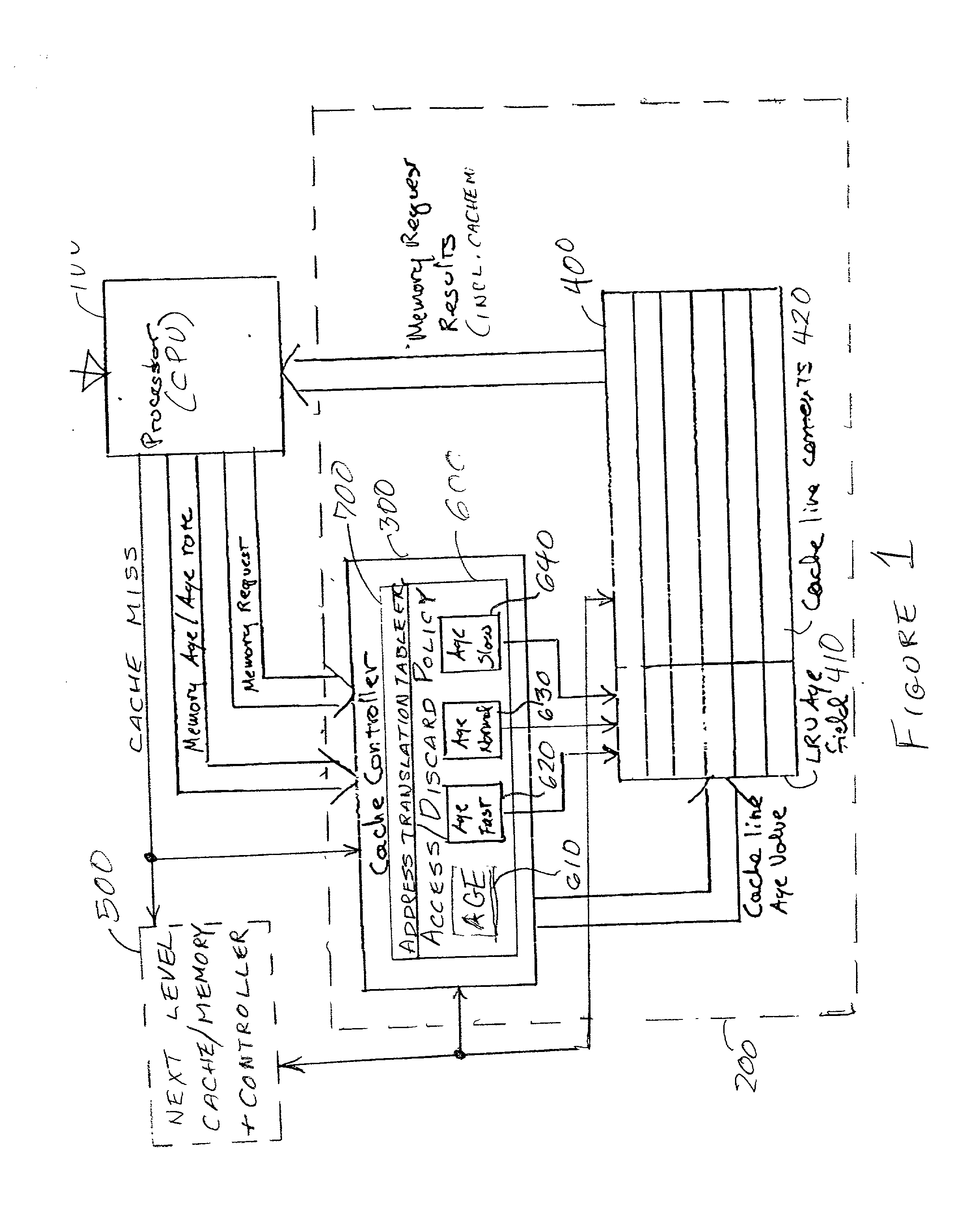
[0021] Referring now to the drawings, and more particularly to FIG. 1, there is shown a high-level block diagram of a portion of a data processing arrangement including a central processing unit (CPU) 100 and a (preferably on-chip) cache 200 including a cache controller 300 and a cache memory 400. A further / next cache level or mass storage memory is depicted at 500 to indicate that the invention can be implemented to advantage at any or all levels of memory / cache associated with the CPU 100. The cache controller 300 preferably includes an autonomous processor 600 for implementing a replacement or access / discard policy to determine the code maintained in the cache memory 400 at any given time. Alternatively, action of the cache memory controller can be controlled or entirely performed by the CPU 100.

[0022] Those skilled in the art may recognize some similarities of the gross organization of CPU 100, cache 200 and a further memory or cache level 500. However, the nature of the cache c...


PUM


Abstract

Fine grained control of cache maintenance resulting in improved cache hit rate and processor performance by storing age values and aging rates for respective code lines stored in the cache to direct performance of a least recently used (LRU) strategy for casting out lines of code from the cache which become less likely, over time, of being needed by a processor, thus supporting improved performance of a processor accessing the cache. The invention is implemented by the provision for entry of an arbitrary age value when a corresponding code line is initially stored in or accessed from the cache and control of the frequency or rate at which the age of each code is incremented in response to a limited set of command instructions which may be placed in a program manually or automatically using an optimizing compiler.

Description

[0001] 1. Field of the Invention[0002] The present invention generally relates to management of contents of cache memories associated with digital data processors and, more particularly, to optimizing processor performance for particular applications by optimizing cache content.[0003] 2. Description of the Prior Art[0004] Digital data processors have come into widespread use and extremely high performance is now generally expected. Therefore, current data processors are capable of operating at very high clock speeds and short cycle times. At the same time, to meet additional demands for increased functionality of applications programs and sophisticated graphical user interfaces (GUIs), the amount of code in an application program has been generally increasing during recent years.[0005] To execute a program, a processor must have access to data on which operations are to be performed and instructions which define and direct the performance of particular operations. The data and instr...

Claims


Application Information

Patent Timeline
Patent Type & Authority Applications(United States)
IPC IPC(8): G06F12/12
CPCG06F12/123Y02B60/1225G06F12/127Y02D10/00
Inventor DEAN, ALVAR A.GOODNOW, KENNETH J.GUTWIN, PAUL T.MAHIN, STEPHEN W.PRICER, W. DAVID
Owner IBM CORP
Learn More