Method and apparatus for aircraft-based simulation of variable accelerations and reduced gravity conditions

a technology applied in the field of aircraft-based simulation of variable acceleration and reduced gravity conditions, can solve the problems of not being suitable for centrifuge methods, unable to achieve accelerations less than 1 g, and being difficult to simulate the small gravitational acceleration of only 3.72 m/s

Inactive Publication Date: 2002-11-07
ASTRIUM GMBH
View PDF15 Cites 7 Cited by
  • Summary
  • Abstract
  • Description
  • Claims
  • Application Information

AI Technical Summary

Problems solved by technology

While the atmospheric or environmental conditions (e.g. temperature, gas composition, pressure, etc.) prevailing on the surface of Mars can be relatively easily simulated in suitable test chambers, it is rather problematic to simulate the small gravitational acceleration of only 3.72 m / s.sup.2, i.e. approximately 1 / 3 g (or somewhat more accurately 3 / 8 g), which prevails on the surface of Mars.
These centrifuge methods cannot, however, realize accelerations less than 1 g, because they always involve superimposing an additional acceleration on the basic 1 g gravitational acceleration.
Thus, such methods are not suitable for the field of application of interest for the present invention.
Trying to achieve longer fall times with a higher tower or the like is impractical.
Moreover, the test capsule released from such a drop or fall tower typically must be subjected to a rather hard or intensive braking phase with a considerable braking shock at the end of the fall time.
Such a braking shock exerts a correspondingly strong deceleration onto the test capsule, which can damage any equipment in the test capsule and could endanger test personnel if they were to be present in the test capsule.
It is further significant that manned atmospheric fall capsules have not yet become known in the prior art, presumably because their realization would be extremely complicated and costly due to the safety requirements that would have to be met.

Method used


Image

  • Method and apparatus for aircraft-based simulation of variable accelerations and reduced gravity conditions
  • Method and apparatus for aircraft-based simulation of variable accelerations and reduced gravity conditions
  • Method and apparatus for aircraft-based simulation of variable accelerations and reduced gravity conditions

Examples


Embodiment Construction

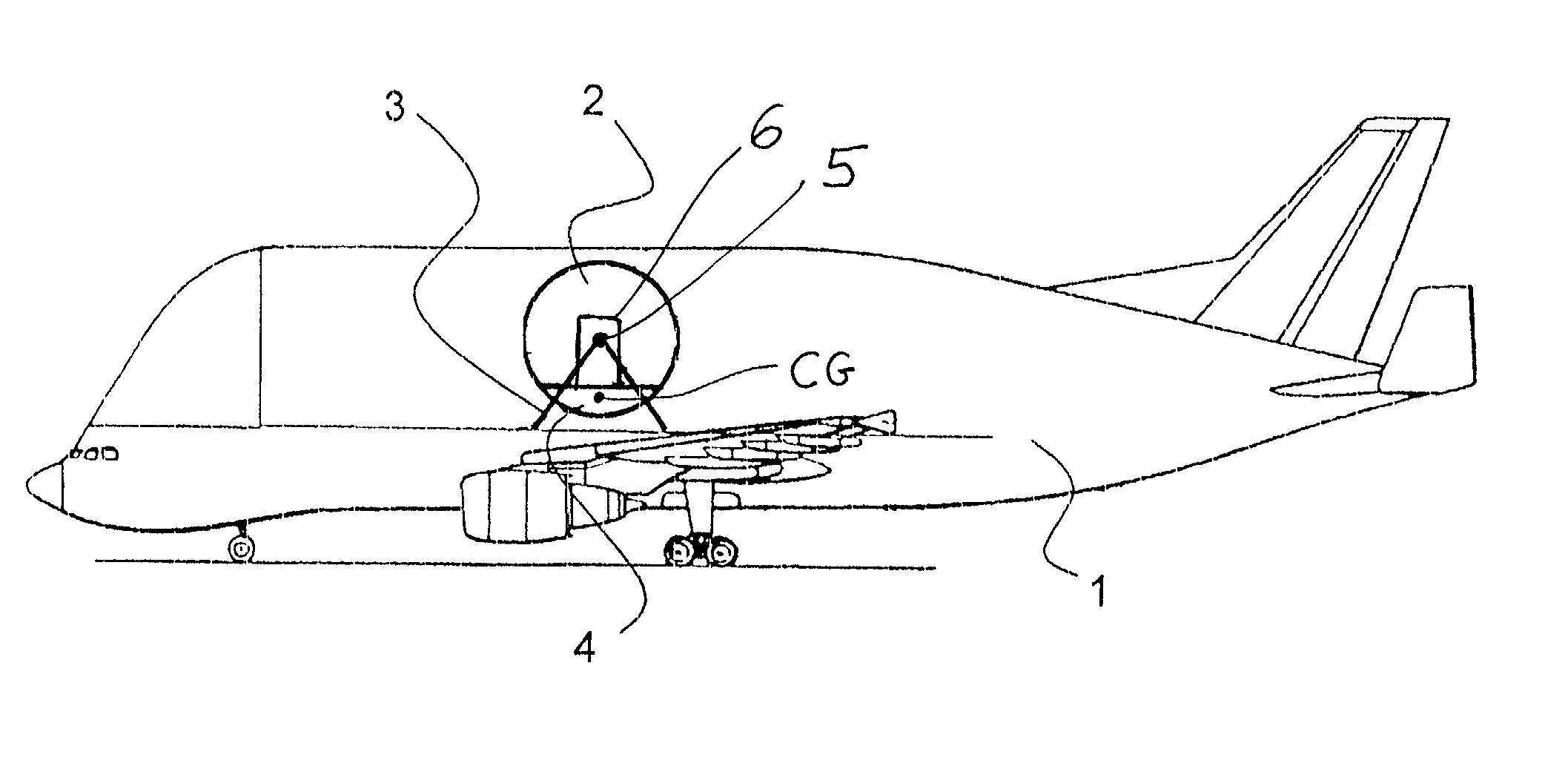
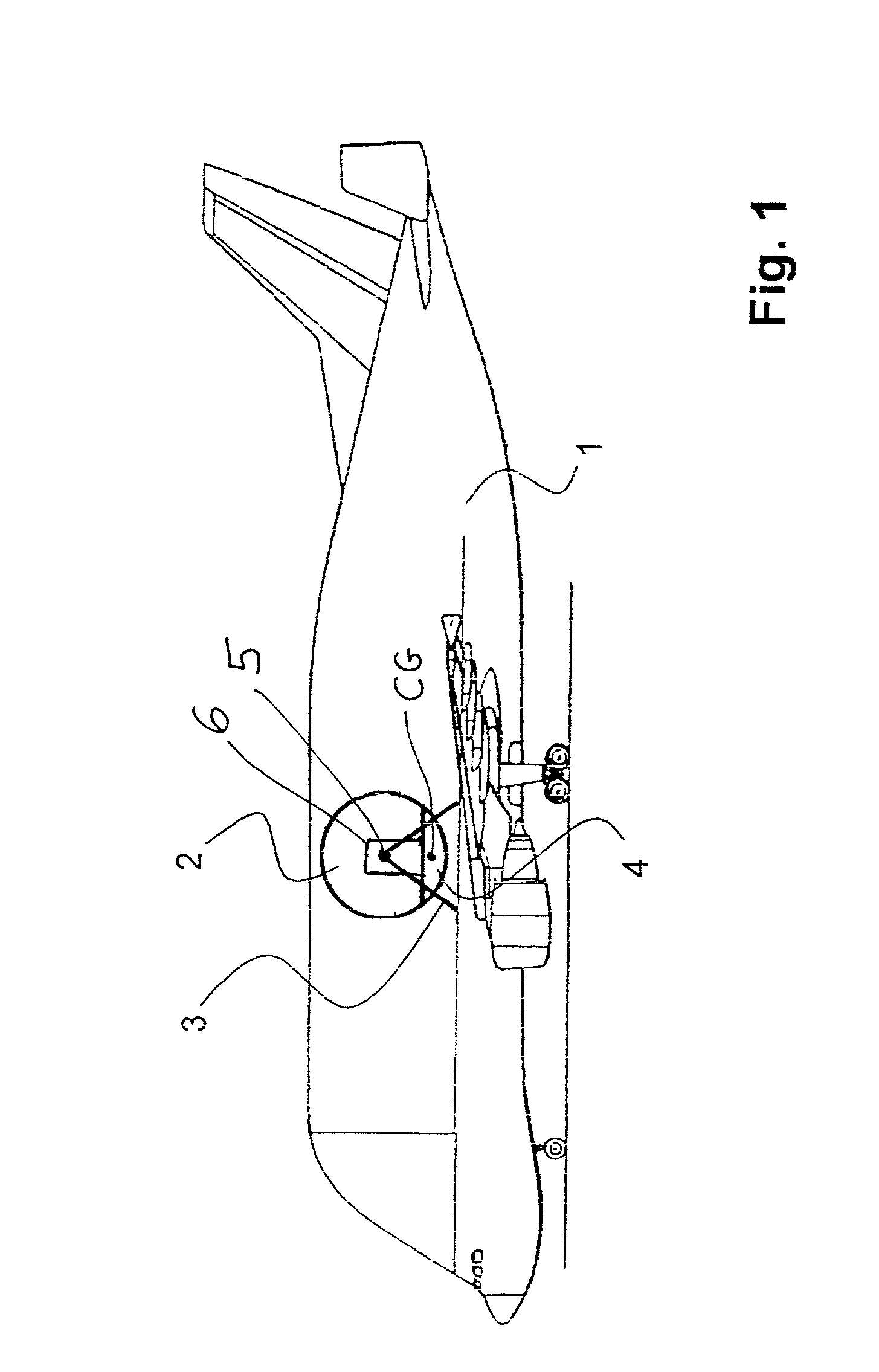
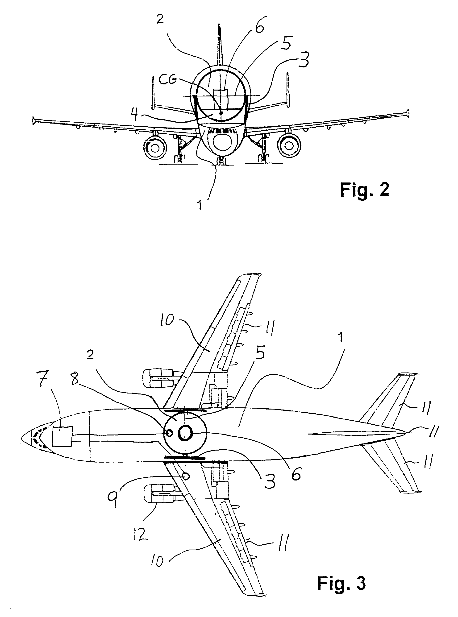
[0020] A large volume or high capacity transport aircraft 1 has a payload or cargo space with a test chamber 2 installed therein. The test chamber 2 is generally in the form of a sphere with a diameter of about 3 to 4 m installed therein. Other test chamber geometries could be used alternatively, but a spherical test chamber is well suited to maintaining a pressure-tight enclosure to establish a desired atmospheric gas composition and pressure within the test chamber 2. By means of suitable equipment 16, such as cooling devices, heaters, gas supply tanks, a gas compressor, regulating valves, and the like, preferably arranged in an underfloor area 4 of the test chamber 2, it is possible to establish an environment within the chamber 2 that realistically simulates environmental conditions prevailing in the atmosphere of Mars, for example with regard to the gas composition of the atmosphere (e.g. about 95 vol. % carbon dioxide, about 2.7 vol. % nitrogen, about 1.6 vol. % argon, and sma...


PUM


Abstract

A test chamber is pivotably suspended in an aircraft, so that the center of gravity of the test chamber always self-actingly orients itself in the direction of the effective residual acceleration. To simulate a selected acceleration greater than 0 g and less than 1 g, the aircraft is flown along a parabolic flight path with a downward vertical acceleration such that the difference between Earth's gravitational acceleration and the aircraft's acceleration corresponds to the selected acceleration to be simulated. To simulate gravitational conditions on Mars, the aircraft is flown with a downward vertical acceleration of about 2/3 g, so that the residual acceleration acting on the test chamber is about 1/3g. The atmospheric conditions, such as the gas composition, pressure and temperature, of Mars can also be established in the test chamber.

Description

PRIORITY CLAIM[0001] This application is based on and claims the priority under 35 U.S.C. .sctn.119 of German Patent Application 101 06 516.7, filed on Feb. 13, 2001, the entire disclosure of which is incorporated herein by reference.[0002] The invention relates to a method and an apparatus for simulating variable accelerations between 0 g and 1 g (where "g" is Earth's gravitational acceleration), and especially for simulating reduced gravity conditions, for example as exist on the surface of planets such as Mars. The invention especially relates to carrying out such simulations using a parabolic flight path of an aircraft.BACKGROUND INFORMATION[0003] In order to simulate, test and evaluate the operation of devices, equipment and processes that are to operate on the surface of the planet Mars, in the scope of a manned or unmanned mission, it is necessary to simulate the environmental conditions prevailing on Mars as completely and accurately as possible here on Earth. While the atmo...

Claims


Application Information

Patent Timeline
Patent Type & Authority Applications(United States)
IPC IPC(8): B64D47/00B64G7/00
CPCB64G7/00B64D47/00
Inventor RANSOM, STEPHENZIER, MANFRED
Owner ASTRIUM GMBH
Why Eureka
Try Eureka