Eureka AIR delivers breakthrough ideas for toughest innovation challenges, trusted by R&D personnel around the world.

Integrated decoupling capacitors

Inactive Publication Date: 2002-11-14
CONVERSANT INTPROP MANAGEMENT INC
View PDF0 Cites 56 Cited by
  • Summary
  • Abstract
  • Description
  • Claims
  • Application Information

AI Technical Summary

Benefits of technology

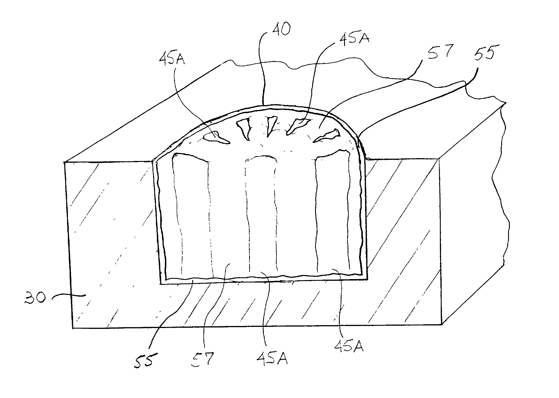
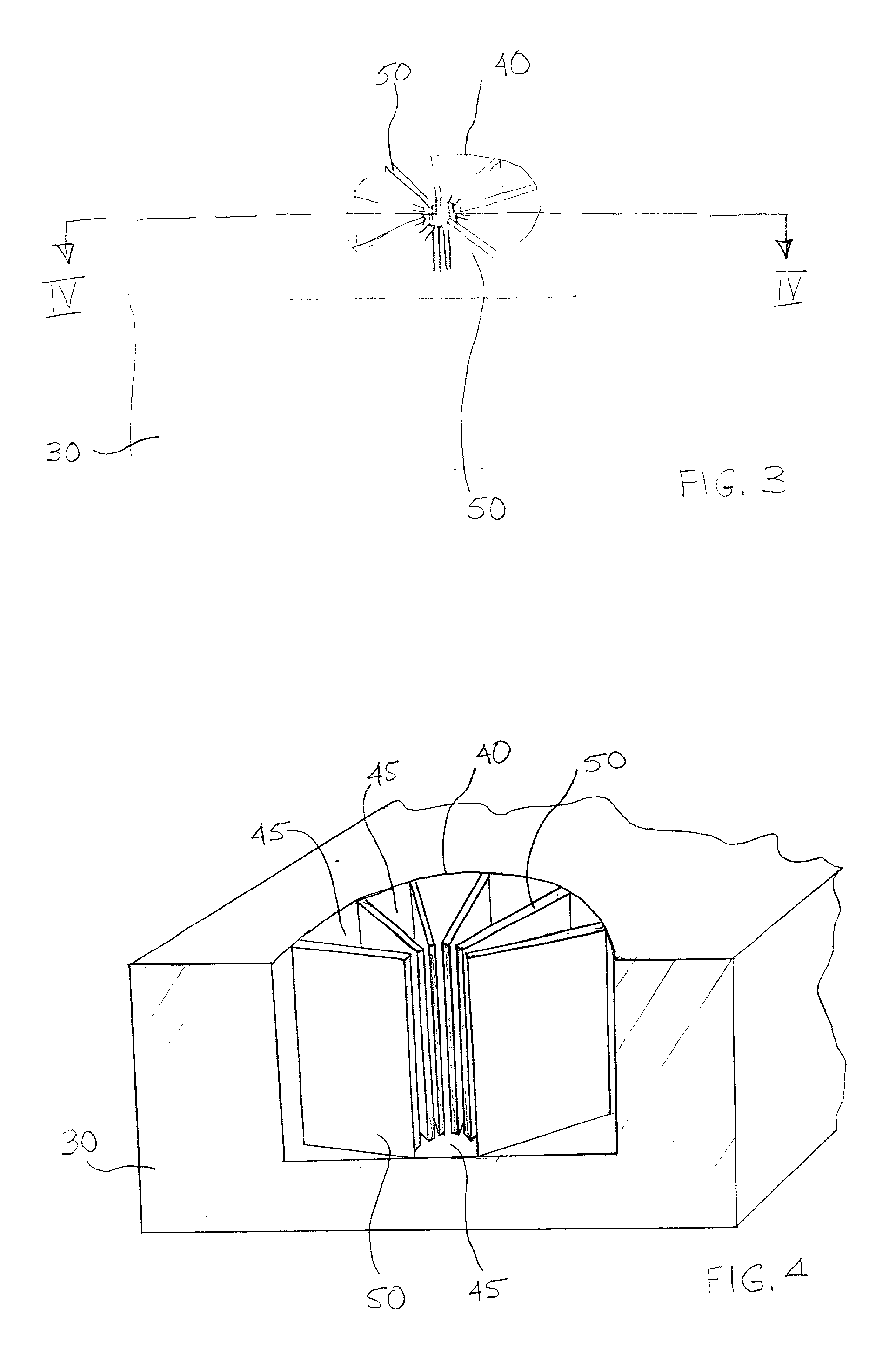
[0007] A method of forming decoupling capacitors for reducing undesirable noise in an integrated circuit is disclosed, comprising forming an opening within a substrate, where the opening contains fin-like spacers, depositing a dielectric material over the spacers, depositing an electrode material over the dielectric material, depositing an insulative material over the electrode material, and forming integrated circuit components over the insulative material.

Problems solved by technology

The inductive voltage drop can nevertheless be substantial, causing high frequency noise that is superimposed upon the power supply voltage.
For future generations of components with multi-GHz chips, in particular, noise in the power and ground lines increasingly becomes a problem.
The existing methods for fabricating decoupling capacitors, however, fall short of increasing industry demands that require new performance criteria from supporting components, such as better location within the integrated circuit and higher performance parameters in high-speed environments.

Method used


Image

  • Integrated decoupling capacitors
  • Integrated decoupling capacitors
  • Integrated decoupling capacitors

Examples


Embodiment Construction

[0032] In the following detailed description, reference is made to various specific embodiments in which the invention may be practiced. These embodiments are described with sufficient detail to enable those skilled in the art to practice the invention, and it is to be understood that other embodiments may be employed, and that structural and electrical changes may be made without departing from the spirit or scope of the present invention.

[0033] The term "substrate" used in the following description may include any semiconductor-based structure that has a semiconductor surface. The term should be understood to include silicon, silicon-on-insulator (SOI), silicon-on-sapphire (SOS), silicon-on-nothing (SON), doped semiconductors, epitaxial layers of silicon supported by a base semiconductor foundation, and other semiconductor structures. The semiconductor need not be silicon-based. The semiconductor could be silicon-germanium, germanium, or gallium arsenide. When reference is made to...


PUM


Abstract

A method for fabricating buried decoupling capacitors in an integrated circuit is disclosed. The method forms decoupling capacitors by creating an opening within a substrate which has fin-like spacers, depositing a dielectric material over the spacers, depositing an electrode material over the dielectric material, depositing an insulative material over the electrode material, and forming integrated circuit components over the insulative material.

Description

FIELD OF THE INVENTION[0001] The present invention relates to the field of integrated circuits and, in particular, to a method of fabricating compact decoupling capacitors within integrated circuits.BACKGROUND OF THE INVENTION[0002] Integrated circuits, particularly those used in computer systems, continuously become more powerful and operate at faster speeds. To supply power to circuit components, metal layers dedicated to power supply distribution are formed in the circuits in order to maintain a low inductive voltage drop. The inductive voltage drop can nevertheless be substantial, causing high frequency noise that is superimposed upon the power supply voltage. For future generations of components with multi-GHz chips, in particular, noise in the power and ground lines increasingly becomes a problem.[0003] Bypass capacitors or decoupling capacitors, which act as a charge reservoir, provide an effective way to suppress the power distribution noise. Additionally, decoupling capacit...

Claims


Application Information

Patent Timeline
IPC IPC(8): H01L21/02H01L21/334H01L29/94
CPCH01L28/90H01L29/945H01L29/66181
Inventor AHN, KIE Y.FORBES, LEONARD
Owner CONVERSANT INTPROP MANAGEMENT INC
Why Eureka
Eureka Blog
Learn More