Optical switch and optical waveguide apparatus

a technology of optical waveguide and optical switch, which is applied in the direction of optics, optical light guides, instruments, etc., can solve the problems of insufficient contact of the optical switch as described above, and achieve the effect of avoiding the occurrence of a single core 105 conta

Inactive Publication Date: 2002-11-14
MITSUBISHI ELECTRIC CORP
View PDF3 Cites 124 Cited by
  • Summary
  • Abstract
  • Description
  • Claims
  • Application Information

AI Technical Summary

Problems solved by technology

Such an optical switch as described above has a problem when it switches from the OFF state to the ON state.
This has caused a problem such that the contact between slit end surfaces 102a of film polymer 102 is insufficient, and sufficient contact of core 105 cannot be obtained.

Method used


Image

  • Optical switch and optical waveguide apparatus
  • Optical switch and optical waveguide apparatus
  • Optical switch and optical waveguide apparatus

Examples


first embodiment

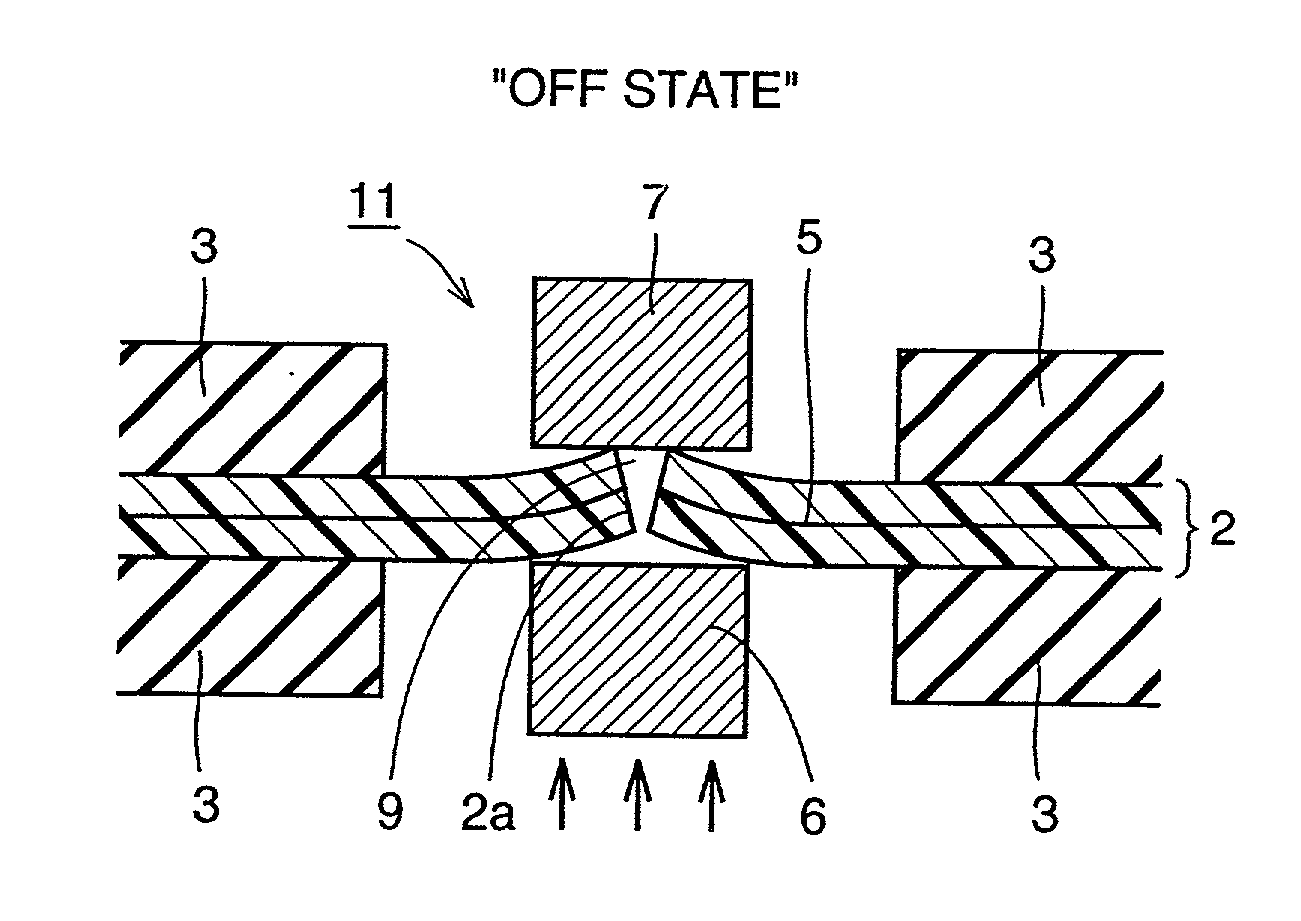
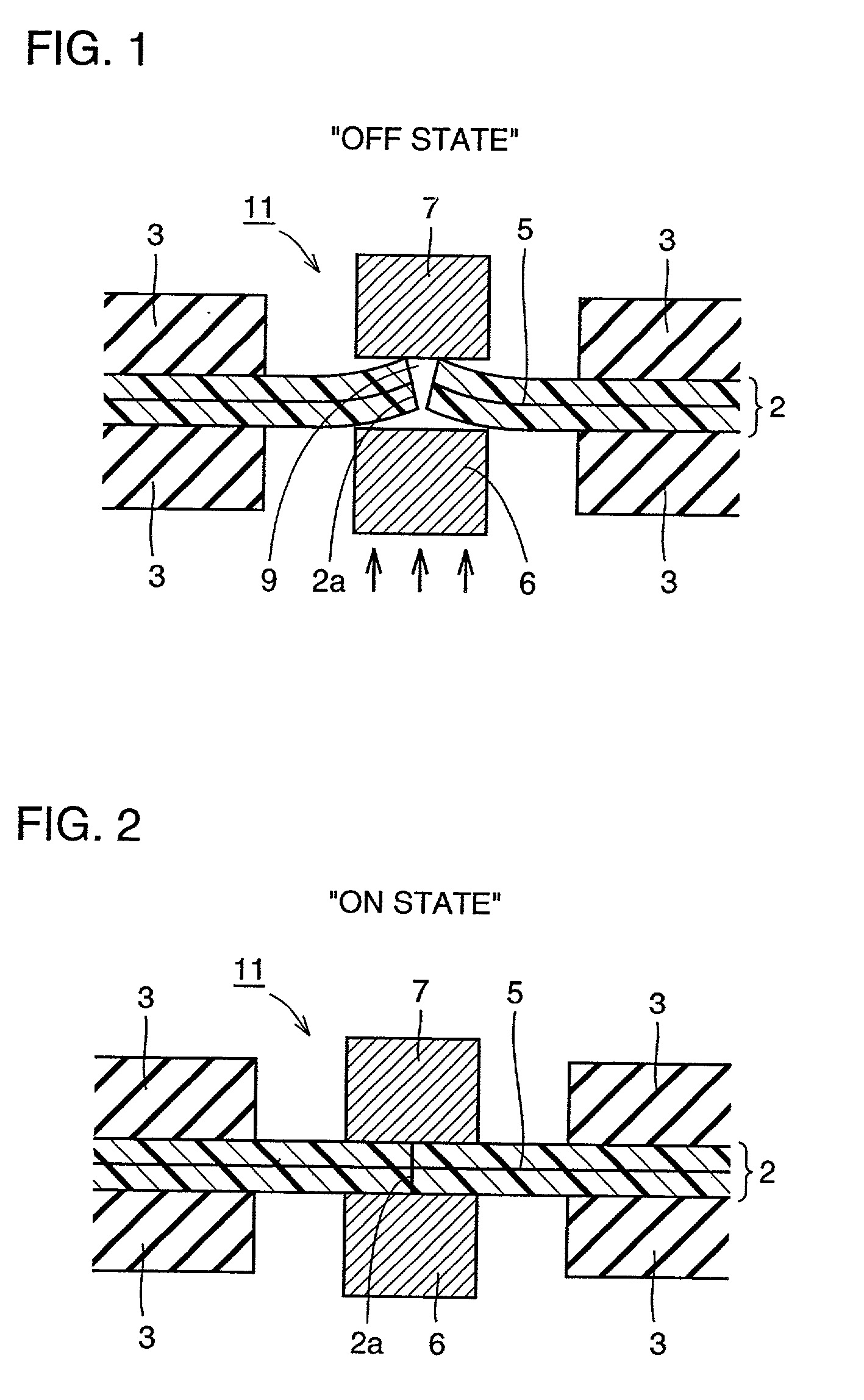
[0077] FIGS. 1 and 2 are section views each taken along the direction of a waveguide in a waveguide optical switch according to the present invention. FIG. 1 shows an OFF state whereas FIG. 2 shows an ON state. A core 5, i.e. the waveguide, is enclosed in a film polymer 2, and film polymer 2 is flattened interposed between rigid holding plates 3. Light is trapped in the core 5 portion of film polymer 2, and is propagated therein with a part of the light exuding to the film polymer. A slit portion is arranged at a crossing portion 11 where cores of waveguides cross with one another, such that the slit diagonally traverse the waveguides. The optical switch is constituted by the slit portion and two push rods (driving members) 6,7 arranged so as to interpose the film polymer from upper and lower sides thereof.

[0078] In the OFF state shown in FIG. 1, a gap 9 is formed between end surfaces 2a of the film polymer. In this OFF state, the light propagated in one core and the film polymer ca...

second embodiment

[0083] In a waveguide optical switch according to the second embodiment of the present invention, a piezoelectric element, i.e. an element constituted by a piezoelectric material that induces distortion or stress by applying a voltage, is used for at least one of a driver (driving mechanism) or a driver assistant member. For the piezoelectric element, barium titanate (BaTiO.sub.3), lead zirconate titanate (PbZrO.sub.3, PbTiO.sub.3), niobate (NaNbO.sub.3, KnbO.sub.3, PbNb.sub.2O.sub.6), rock crystal, Rochelle salt, LiTaO.sub.3, LiNbO.sub.3 and so forth may be used.

[0084] Using the piezoelectric element, a pressure power of hundreds of newtons can be obtained by a normal voltage application. Thus, a simple mechanical structure can realize alternate switching between the state where the end surfaces are in contact with each other (ON state) and the state where a gap is arranged between the end surfaces (OFF state).

third embodiment

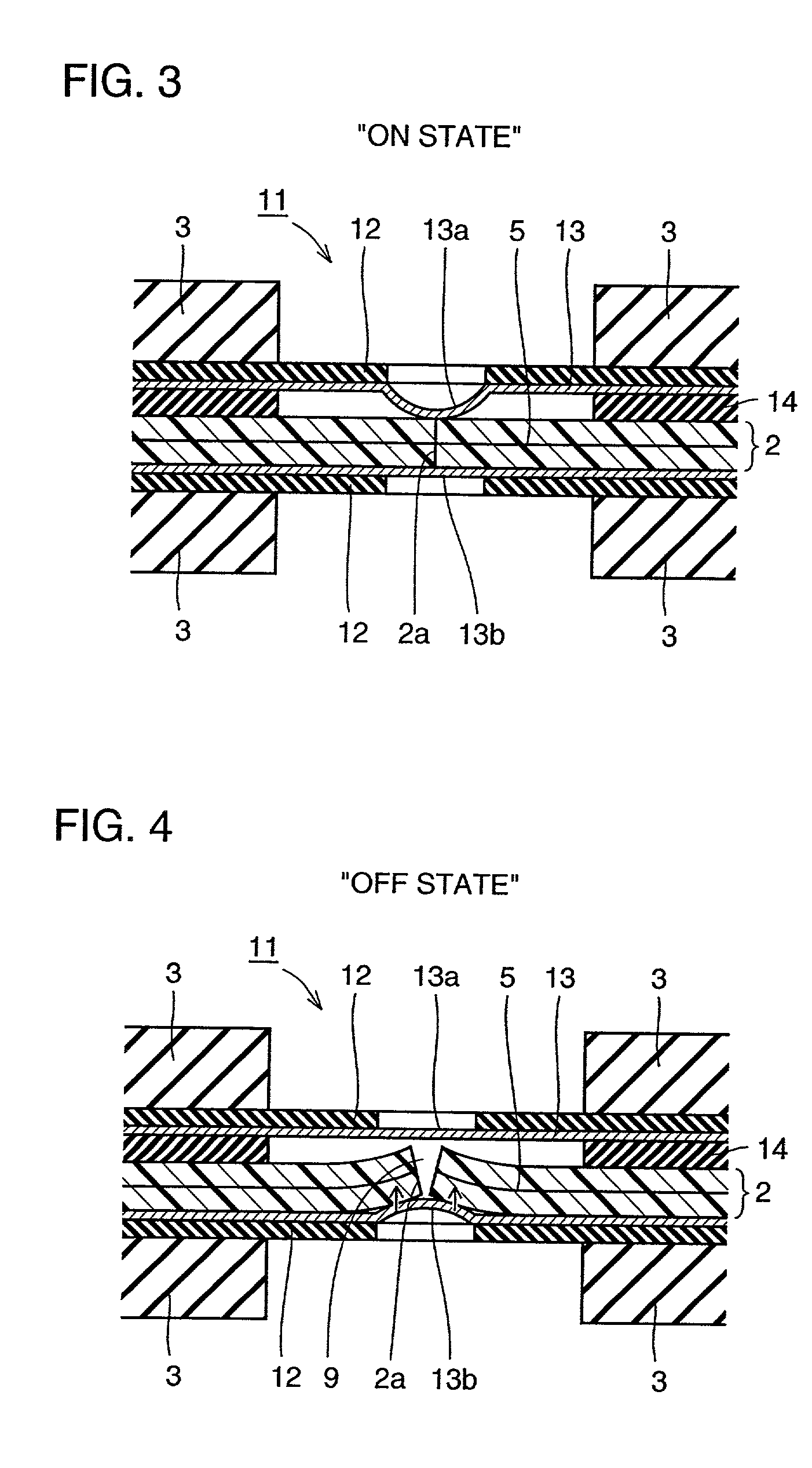
[0085] FIGS. 3 and 4 are section views each taken along a waveguide and showing a waveguide optical switch according to the third embodiment of the present invention. FIG. 3 shows the ON state where end surfaces 2a are in contact with each other, whereas FIG. 4 shows the OFF state where gap 9 is formed between the end surfaces. In the present embodiment, artificial muscles are used for alternate switching between the contact state and the separate state of the end surfaces. That is, the artificial muscles arranged on both the upper and lower sides of the film polymer are used in place of two push rods 6, 7 used in the first embodiment.

[0086] As shown in FIGS. 3 and 4, an artificial muscle actuator includes, for example, a sheet-like apertured frame 12 and a sheet-like electrode-attached elastic body 13, and a spacer 14 is further arranged on the upper side of the film polymer. Electrode-attached elastic bodies 13a, 13b of electrode-attached elastic body 13, which are arranged at a p...


PUM


Abstract

Highly reliable optical switch and optical waveguide apparatus are obtained, which can perform stable and reliable ON/OFF operations for optical connection at a waveguide crossing portion. The optical switch is provided in an optical waveguide apparatus including a waveguide propagating light and a waveguide housing sheet enclosing the waveguide, and includes a slit portion slitting to traverse the waveguide; a driver performing driving action onto the slit portion; and a driver assistant member interposing the slit portion between the driver assistant member and the driver to assist the driver, the driver and driver assistant member pushing open the slit portion to provide a gap, and bring the slit portion into contact to connect waveguides.

Description

[0001] 1. Field of the Invention[0002] The present invention relates to an optical switch and an optical waveguide apparatus used for switching of optical connection in an optical communication system.[0003] 2. Description of the Background Art[0004] Referring to FIG. 26, an optical switch is provided for an optical waveguide 105 of a film polymer 102, i.e. a waveguide housing sheet 102, held between holding plates 103. Referring to FIG. 27, in an optical connection ON state (hereinafter simply referred to as ON state) in which a driving mechanism (push rod) 106 is not pushed at the crossing portion of the waveguide, waveguide housing sheet 102 keeps slit end surfaces 102a in contact with each other at a slit portion. Therefore, a core, i.e. waveguide 105, is also held in contact at the slit portion. Hence, the light arrived at the contact slit portion passed through the slit portion without its direction changed.[0005] On the other hand, in an optical connection OFF state (hereinaf...

Claims


Application Information

Patent Timeline
Patent Type & Authority Applications(United States)
IPC IPC(8): G02B26/08G02B6/35
CPCG02B6/3502G02B6/3552G02B6/3546
Inventor SAITO, TAKESHI
Owner MITSUBISHI ELECTRIC CORP
Why Eureka
Try Eureka