Process for producing resonant tag

a technology of resonant tags and die stamping, which is applied in the direction of magnets, printed circuit assembling, magnetic bodies, etc., can solve the problems of metal foil and carrier sheets having to be separated with difficulty, and the die stamping is not so advantageous in other cases

Inactive Publication Date: 2002-11-21
NOVATRON ELECTRONICS HANGZHOU
View PDF0 Cites 10 Cited by
  • Summary
  • Abstract
  • Description
  • Claims
  • Application Information

AI Technical Summary

Problems solved by technology

Thus, the die stamping is applicable to laminate a metal foil with strength to some degree on a solid base material, whereas the die stamping is not so advantageous for other cases.
Thus, that aluminum foil may be broken or the base sheet may be also stamped out during stamping out or transferring the foil, so that the resonant tag using the die stamping has not been put into practical use in the current state.
However, this process has such problems as (1) the additional step of laminating the metal foil on the carrier sheet is required; (2) the metal foil and the carrier sheet must be separated with difficulty; (3) when the stamped-out shape is discontinuous such as round, the separation between the stamped-out portion and the non stamped-out portion is difficu

Method used


Image

  • Process for producing resonant tag
  • Process for producing resonant tag
  • Process for producing resonant tag

Examples


Embodiment Construction

[0076]

1 Size of resonant tag: 40 .times. 40 mm (dimension which becomes an outer periphery of the circuit) Resonant frequency: 8.2 MHz

[0077] Under the above-mentioned conditions, the resonant tag of the present invention (Example) and the conventional resonant tag were manufactured and the performances of the manufactured resonant tags were compared.

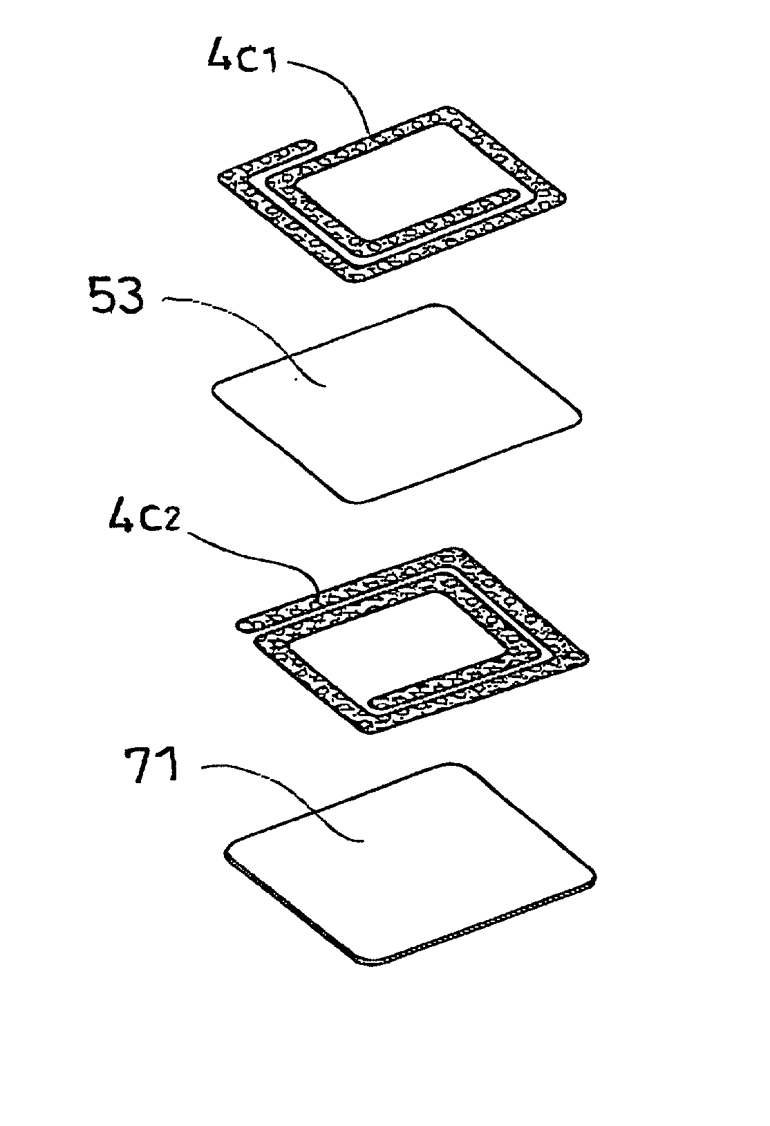
[0078] The resonant tag of the Example is a resonant tag of the both-face coil type as shown in FIG. 4D. The Comparative Example is a resonant tag in one-face coil type as shown in FIG. 7.

[0079] The constitutions and properties are shown in Table 1.

2 TABLE 1 Comparative Example Example Coil material aluminum foil aluminum foil thickness (surface / back) 50 .mu.m / 10 .mu.m 40 .mu.m / 40 .mu.m number of winding 8 2 / 1 (surface / back) Dielectric capacitor 20 .mu.mPE film 3 .mu.m coated resin film area / volume 121 mm.sup.2 / 123 pF 727.3 mm.sup.2 / 4937 pF L (inductance) 3.06 .mu.H 0.154 .mu.H Length of coil 980 mm 284 mm Coil resistance 0.6860 .OMEGA. ...


PUM

PropertyMeasurementUnit
Lengthaaaaaaaaaa
Electrical resistanceaaaaaaaaaa
Lengthaaaaaaaaaa

Abstract

A process for producing a resonant tag, wherein a metal foil having a thermal adhesion adhesive applied to at least one face thereof is stamped out into a circuit-like shape and is adhered to a base sheet, the process comprising: stamping out the metal foil into a predetermined shaped metal foil portion (4c) while being passed through a die roll (1) having thereon a stamping blade with a predetermined shape and a transfer roll (2) in contact with the die roll (1) which functions also as a die back-up roll; holding this metal foil portion obtained by the stamping-out operation onto the surface of the transfer roll by suction holes formed in the transfer roll; and thermally adhering the stamped metal foil portion to the base sheet (7) in contact with the transfer roll (2) at its another face by an adhesive roll (3) in contact with the transfer roll through the base sheet. The present invention has such advantages as no damage to the base sheet since the stamping-out operation for the metal foil and the thermal adhesion operation thereof to the base sheet are carried out in separate positions, and no requirement of carrier sheet because the resultant metal foil portion obtained by the stamping-out operation is sucked and held onto the surface of the transfer roll.

Description

[0001] 1. Field of the Invention[0002] The present invention relates to a process for producing a resonant tag equipped with a resonant frequency circuit which resonates with a radio wave transmitted at a particular frequency from a detector.[0003] 2. Description of the Related Art[0004] As is well known, resonant tag is a tag equipped with a resonant circuit which resonates with a radio wave transmitted at a particular frequency. Thus, when the resonant tag is brought into an area in which the radio wave of the particular frequency is transmitted, the resonant tag readily reacts to operate a buzzer or an alert lamp of a detector. Thus, to avoid shoplifting, the resonant tags are attached to goods and the like in department stores, discount stores, rental shops for video tapes, compact disk (CD) shops, etc.[0005] Basically, a resonant tag is composed of a plastic film (as a dielectric), having a spiral (or a coil-shaped) circuit (hereinafter referred to as a "coil circuit") on at le...

Claims


Application Information

Patent Timeline
IPC IPC(8): G06K19/077G08B13/24H01F5/00H01F41/04H05K3/04
CPCB32B2425/00Y10T29/49073G06K19/07718G06K19/07749G08B13/242G08B13/2431G08B13/2437G08B13/244H01F5/003H01F41/041H05K3/041Y10S428/901Y10T29/49018Y10T428/24917Y10T428/2817Y10T29/4913Y10T29/49155Y10T29/49016Y10T29/532Y10T29/49002B32B2519/02Y10T428/31681
Inventor UCHIBORI, SHINYAMIZUKAWA, TAKAAKIHATANAKA, YOSHINORI
Owner NOVATRON ELECTRONICS HANGZHOU
Why Eureka
Try Eureka