Method for aligning electron beam projection lithography tool

a technology of electron beam and exposure tool, which is applied in the field of electron beam projection lithography exposure tool, can solve the problems of only being able to expose the probe-forming tool, requiring billions of pixels, and not having sufficient throughput from the probe-forming tool to meet mass-manufacturing requirements

Inactive Publication Date: 2002-11-28
NIKON CORP
View PDF0 Cites 7 Cited by
  • Summary
  • Abstract
  • Description
  • Claims
  • Application Information

AI Technical Summary

Problems solved by technology

However, probe-forming tools are only capable of exposing a single spot of perhaps as many as a few dozen or, at most, a few hundred pixels at a time.
Modern integrated circuit designs, however, may include billions of pixels and sufficient throughput is not available from probe-forming tools to meet mass-manufacturing requirements even when individual exposures can be made at extremely high repetition rates.
However, the variety of effects each element may have, the number ...

Method used


Image

  • Method for aligning electron beam projection lithography tool
  • Method for aligning electron beam projection lithography tool
  • Method for aligning electron beam projection lithography tool

Examples


Embodiment Construction

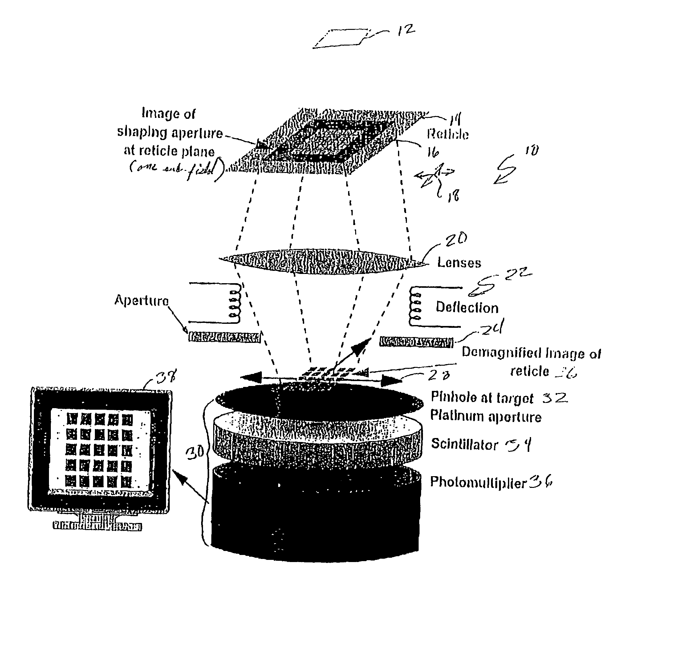
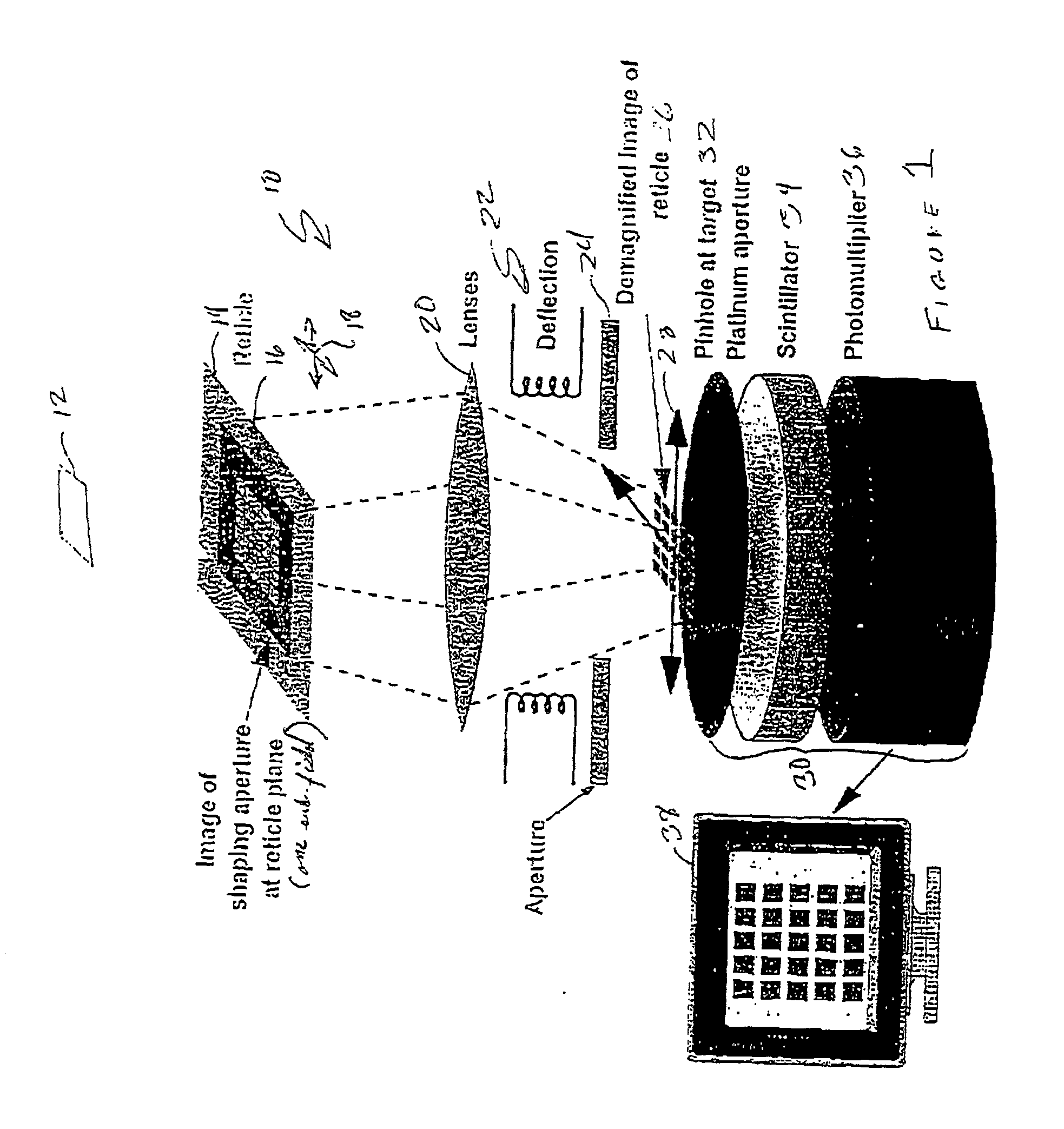
[0019] Referring now to the drawings, and more particularly to FIG. 1, there is shown a portion of the electron beam column of an exemplary and generalized electron beam projection lithography tool 10. A shaping aperture 12 is located below an electron beam source (not shown) and an image of the shaping aperture is focussed at the reticle plane 14 at which the patterned membrane of the reticle 16 can be located. As alluded to above, the reticle 16 can be translated in orthogonal directions by a positioning mechanism schematically indicated by arrows 18.

[0020] Various lenses collectively indicated at 20 are provided to demagnify, rotate and focus the image of a reticle sub-field onto the target plane, as schematically indicated at 26 using a contrast aperture 24. A translation mechanism, schematically indicated by arrows 28 is provided at the target plane.

[0021] In accordance with the invention, a detector 30 is also provided at the target plane. This detector includes a pin-hole 32 ...


PUM


Abstract

A method of aligning elements of an electron beam beam tool such as an electron beam projection lithography tool utilizes a detector such as a pinhole and scintillator over which an image is rastered to provide a real-time display of a projected image at a target plane. A shaping aperture is projected and the detector centered thereon. A reticle sub-field image is then centered on and aligned with the image of the shaping aperture and the compound image thus formed is rotated using deflectors. The compound image is then aligned with movement of a translation device at the target plane using lenses and compound image orientation is corrected by electrical or mechanical rotation of the deflectors. Sub-field size can then be adjusted and any observed further rotation of the compound image may be corrected by reiteration of rotation adjustment with lenses and deflectors, in sequence.

Description

[0001] 1. Field of the Invention[0002] The present invention generally relates to electron beam projection lithography exposure tools and, more particularly, methods for aligning elements forming the electron beam projection column of such tools[0003] 2. Description of the Prior Art[0004] Demands for improved performance and increased manufacturing economy of semiconductor integrated circuits have driven minimum feature size regimes of integrated circuit designs to a small fraction of a micron. Such minimum feature sizes now being developed are beyond the resolution capability of lithographic exposure tools using deep ultraviolet (UV) wavelengths. Therefore, lithographic exposure with electron beams is now being developed and so-called probe-forming electron beam exposure tools have been in use for several years. However, probe-forming tools are only capable of exposing a single spot of perhaps as many as a few dozen or, at most, a few hundred pixels at a time. Modern integrated cir...

Claims


Application Information

Patent Timeline
IPC IPC(8): G03F7/20G03F9/00H01J37/304H01J37/317H01L21/027
CPCB82Y10/00H01J37/3174H01J37/3045B82Y40/00
Inventor GORDON, MICHAEL S.LIEBERMAN, JON E.ROBINSON, CHRISTOPHER F.
Owner NIKON CORP
Why Eureka
Try Eureka