Catadioptric imaging system for broad band microscopy

a broad band microscopy and imaging system technology, applied in the field of optical imaging, can solve the problems of insufficient numerical aperture (na), insufficient field size, and inability to provide accurate imaging performance for light wavelengths below 400 nm

Active Publication Date: 2014-03-18
KLA TENCOR TECH CORP
View PDF24 Cites 7 Cited by
  • Summary
  • Abstract
  • Description
  • Claims
  • Application Information

AI Technical Summary

Benefits of technology

[0018]According to a first aspect of the present design, there is provided an objective employed for use with light energy having a wavelength in a range of approximately 266 to 1000 nanometers. The objective comprises a focusing lens group comprising at least one focusing lens configured to receive said light energy and form focused light energy, a field lens oriented to receive focused light energy from said focusing lens group and provide intermediate light energy, and a Mangin mirror arrangement positioned to receive the intermediate light energy from the field lens and form controlled light energy. Each focusing lens has a diameter of less than approximately 100 millimeters and a maximum corrected field size of approximately 0.15 mm.
[0019]According to a second aspect of the present design, there is provided an objective employed for use with light energy having a wavelength in the range of approximately 157 nanometers through the infrared light range. The objective comprises a focusing lens group configured to receive said light energy and comprising at least one focusing lens, wherein each focusing lens in the focusing lens group has diameter less than approximately 100 millimeters, at least one field lens oriented to receive focused light energy from said focusing lens group and provide intermediate light energy, each field lens having diameter less than approximately 100 millimeters, and a Mangin mirror arrangement positioned to receive the intermediate light energy from the field lens and form controlled light energy, said Mangin mirror arrangement imparting the controlled light energy to a specimen with a numerical aperture in excess of 0.65 and a field size of approximately 0.15 mm.
[0020]According to a third aspect of the present design, there is provided an objective constructed of a single glass material for use with light energy having a wavelength in the range of approximately 157 nanometers through the infrared light range. The object

Problems solved by technology

Certain UV objectives are capable of transmitting light down to a wavelength of 340 nm, but these objectives do not provide accurate imaging performance for light wavelengths below 400 nm.
Of the available objectives, none can be used in a standard microscope system.
They are either too large, have insufficient numerical aperture (NA), or have an insufficient field size.
Certain issues exist with designs similar to that presented in FIG. 1.
First, the field lens group may need to be physically located within a central hole in the large curved catadioptric element, which can make manufacturing difficult and expensive.
Second, the field lens elements in such a design may require at least one glued interface.
In the presence of wavelengths less then 365 nm, reliable glues that can withstand light intensity levels at an internal focus are generally unavailable.
Third, the lens elements in such a design may be located very close to a field plane, thereby requiring a high degree of, or nearly perfect, surface quality and bulk material quality to prevent image degradation.
Large diameter elements frequently make integration into an inspection system difficult and

Method used


Image

  • Catadioptric imaging system for broad band microscopy
  • Catadioptric imaging system for broad band microscopy
  • Catadioptric imaging system for broad band microscopy

Examples


Embodiment Construction

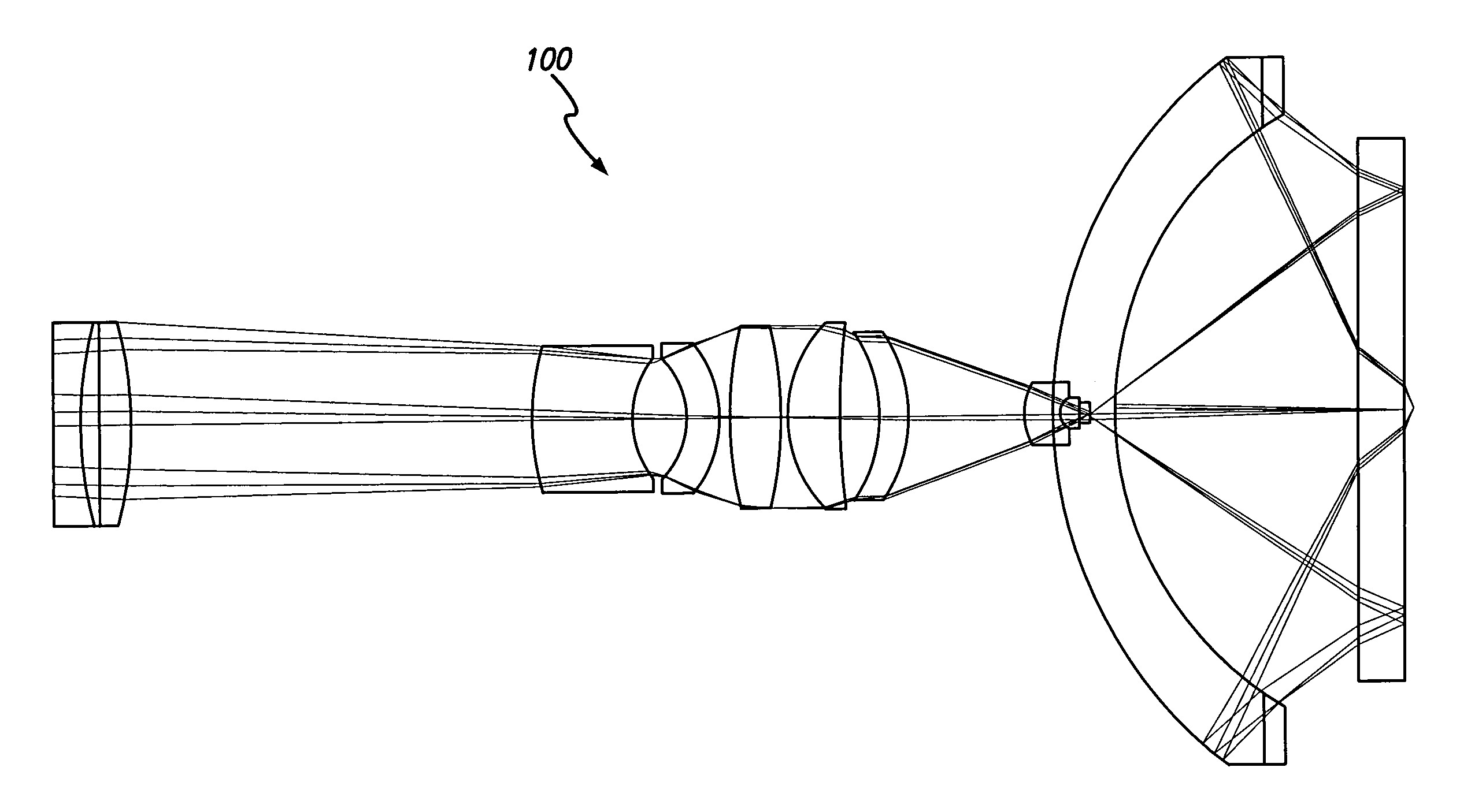
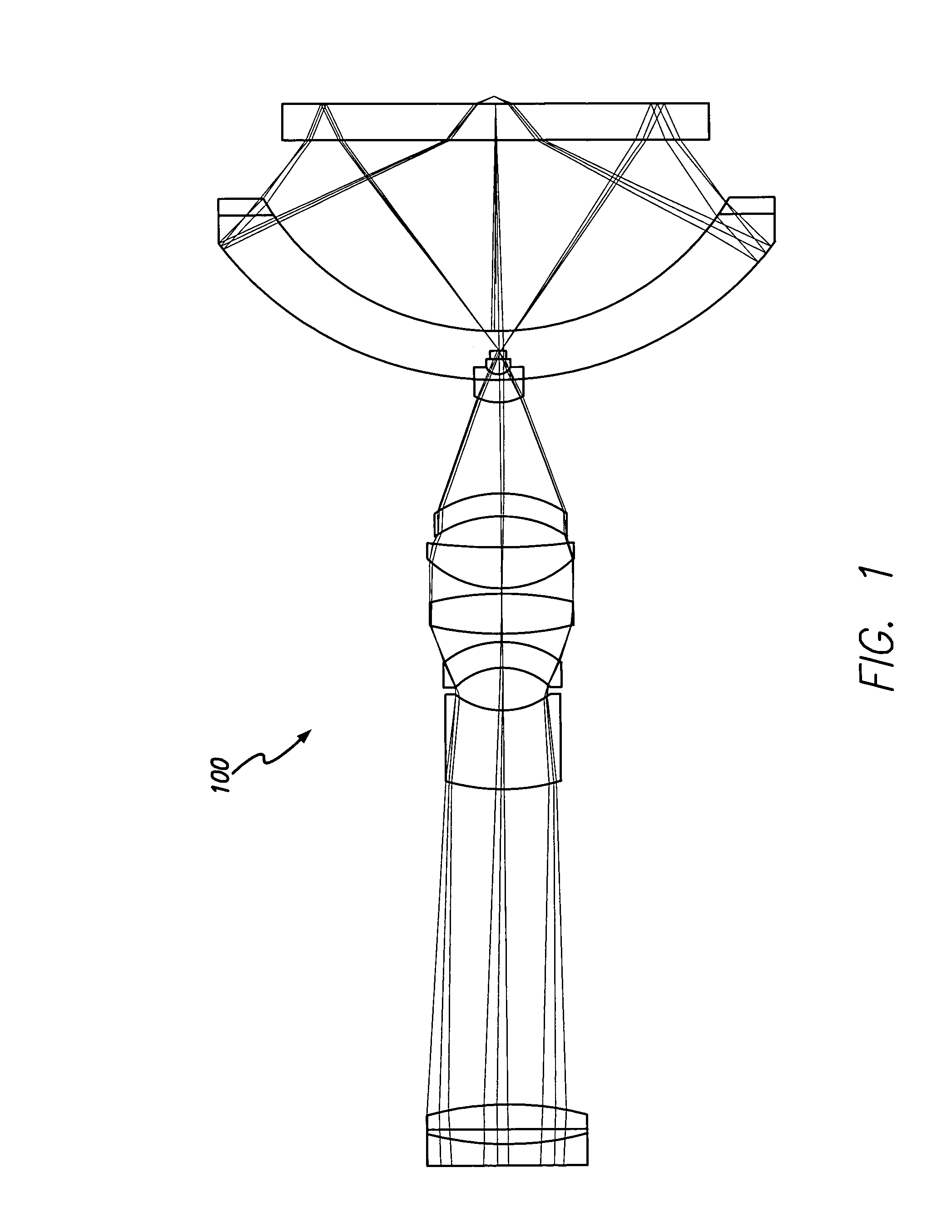
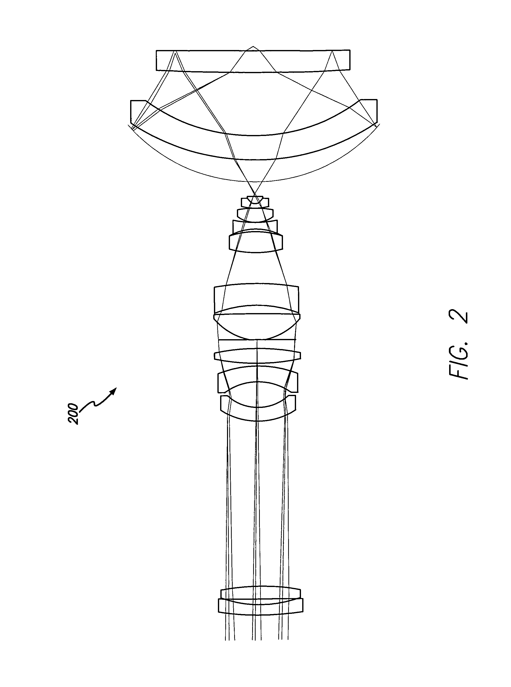
[0038]The present design presents a catadioptric objective corrected over a wavelength range from 266-1000 nm using a single glass material, or in certain circumstances, more than one glass material to improve performance. The objective employed herein may provide particular benefits in the microscopy field. One aspect of the objective design is shown in FIG. 3. The catadioptric objective as shown in FIG. 3 is optimized for broad-band imaging in the UV and visible spectral region, namely approximately 0.266 to 1.000 micron wavelengths. The objective provides relatively high numerical apertures and large object fields. The inventive design presented uses the Schupmann principle in combination with an Offner field lens to correct for axial color and first order lateral color. As shown in the aspect presented in FIG. 3, the field lens group 305 is slightly displaced from the intermediate image 309 to obtain enhanced performance.

[0039]From FIG. 3, the catadioptric group 312 or Mangin mi...


PUM


Abstract

A system and method for inspection is disclosed. The design includes an objective employed for use with light energy having a wavelength in various ranges, including approximately 266 to 1000 nm, 157 nm through infrared, and other ranges. The objective includes a focusing lens group having at least one focusing lens configured to receive light, a field lens oriented to receive focused light energy from said focusing lens group and provide intermediate light energy, and a Mangin mirror arrangement positioned to receive the intermediate light energy from the field lens and form controlled light energy. Each focusing lens has a reduced diameter, such as a diameter of less than approximately 100 mm, and a maximum corrected field size of approximately 0.15 mm. An immersion substance, such as oil, water, or silicone gel, may be employed prior to passing controlled light energy to the specimen inspected.

Description

[0001]This application is a continuation-in-part of U.S. patent application Ser. No. 10 / 434,374, entitled “High Performance Catadioptric Imaging System,” inventors David G. Shafer, et al., filed May 7, 2003 now U.S. Pat. No. 7,180,658, which claims the benefit of U.S. Provisional Patent Application Ser. No. 60 / 449,326, entitled “High Performance, Low Cost Catadioptric Imaging System,” filed Feb. 21, 2003.BACKGROUND OF THE INVENTION[0002]1. Field of the Invention[0003]The present invention relates generally to the field of optical imaging, and more particularly to catadioptric optical systems used for microscopic imaging, inspection, and lithography applications.[0004]2. Description of the Related Art[0005]Many optical systems exist having the ability to inspect or image features on the surface of a specimen. Various applications employ microscopes for imaging purposes, including biology, metrology, semiconductor inspection, and other complex inspection applications wherein high reso...

Claims


Application Information

Patent Timeline
IPC IPC(8): G02B17/00G02B21/00G02B23/00G02BG02B17/08G02B21/02G02B21/04G03F7/20
CPCG02B17/0808G02B17/0812G02B17/0856G02B17/0892G02B21/02G02B21/04G03F7/70225G03F7/70341
Inventor SHAFER, DAVID R.CHUANG, YUNG-HOARMSTRONG, J. JOSEPH
Owner KLA TENCOR TECH CORP
Why Eureka
Try Eureka