Instrument alignment devices and methods

Inactive Publication Date: 2002-12-05
THE BOEING CO
View PDF0 Cites 13 Cited by
  • Summary
  • Abstract
  • Description
  • Claims
  • Application Information

AI Technical Summary

Problems solved by technology

However, strength of the received signal may not be an accurate indicator of the satellite direction.
Furthermore, it is very difficult to align a receiving antenna to a broadband antenna with a narrow beamwidth as the margin for error is very small; physical manipulation of the antenna often results

Method used


Image

  • Instrument alignment devices and methods
  • Instrument alignment devices and methods
  • Instrument alignment devices and methods

Examples


Embodiment Construction

[0023] In the following description, reference is made to the accompanying drawings which form a part hereof, and which is shown, by way of illustration, several embodiments of the present invention. It is understood that other embodiments may be utilized and structural changes may be made without departing from the scope of the present invention.

Apparatus and Method of Antenna Alignment

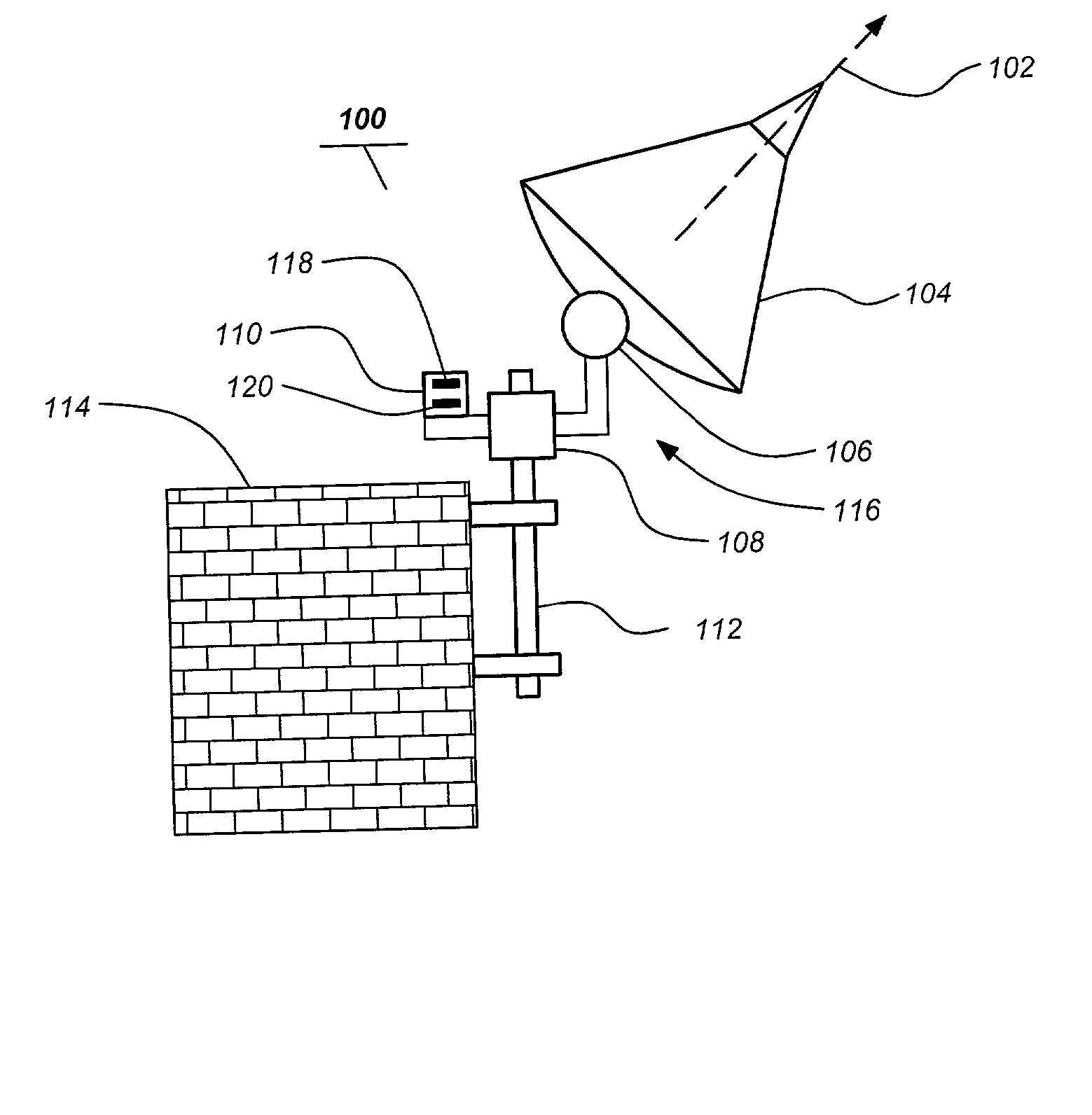
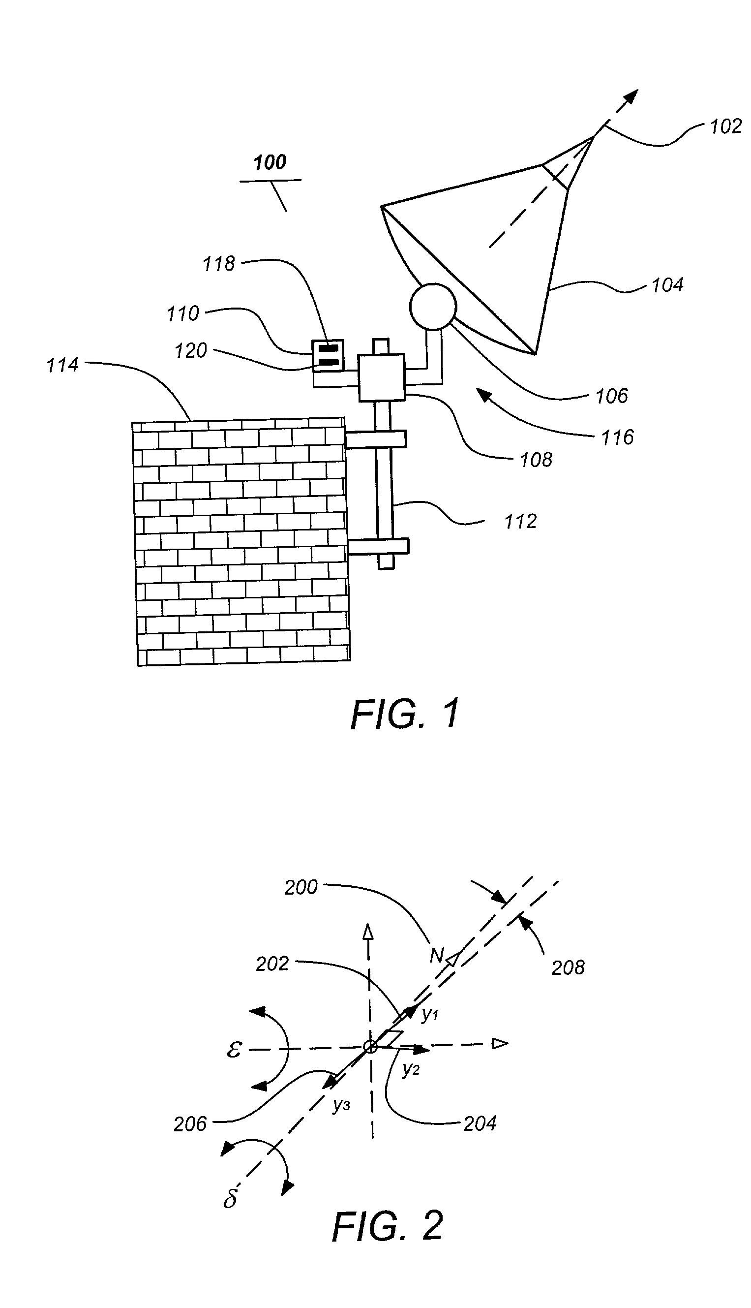
[0024] FIG. 1. illustrates a typical antenna alignment apparatus of one embodiment of the invention. In this embodiment a vertical post 112 is clamped via brackets to a building wall or some other suitable mounting surface of a stable structure 114. The instrument 104 with a boresight 102, a dish antenna for example, is mounted to the vertical 112 post via an azimuth and elevation gimbal 116 comprising an azimuth positioner 108 and an elevation positioner 106. The rotation axis of the azimuth positioner 108 is substantially parallel to the vertical direction and the rotation axis of the elevation pos...


PUM


Abstract

An apparatus and method, for determining an instrument boresight heading. The apparatus comprises an instrument having a boresight, an elevation positioner for positioning the elevation of the instrument boresight having an elevation axis, an azimuth positioner for positioning the azimuth of the instrument boresight having an azimuth axis and a sensor including a gyro having a sensitive axis. The method comprises recording a first output of a gyro of an azimuth positioner having an instrument boresight azimuth heading in a first position, rotating the azimuth positioner to a second position, recording a second output of the gyro and rotating the azimuth positioner to a third position, recording a third output of the gyro and determining the azimuth heading relative to true north from the first, second and third output.

Description

[0001] 1. Field of the Invention[0002] The present invention relates to systems and methods for aligning instrument boresights, and in particular to a system and method for aligning a dish antenna boresight.[0003] 2. Description of the Related Art[0004] Conventional systems and methods of satellite dish alignment require that a user approximate the pointing direction of the antenna from external sightings or a magnetic compass and then search for an antenna signal null. This process must be repeated until an adequate pointing accuracy is achieved.[0005] For example, the antenna alignment method employed by satellite broadcasters such as DirecTV.TM., typical of conventional methods, requires approximate alignment of the antenna toward the satellite based on estimated directions depending upon the user's location on the Earth. Fine alignment of the antenna, e.g. within 0.1.degree., is then achieved in conjunction with the receiver / decoder of the system based upon maximizing the streng...

Claims


Application Information

Patent Timeline
IPC IPC(8): G01C19/42G01C21/16H01Q1/12
CPCG01C19/42H01Q1/125G01C21/16G01C21/166
Inventor CHALLONER, A. DORIAN
Owner THE BOEING CO
Why Eureka
Try Eureka