Wavelength-tunable vertical cavity surface emitting laser and method of making same

a laser and vertical cavity technology, applied in the field of semiconductor vertical cavity surface emitting lasers, can solve the problems bleaching, and achieve the effect of reducing peak absorption

Inactive Publication Date: 2002-12-12
INNOLUME
View PDF0 Cites 22 Cited by
  • Summary
  • Abstract
  • Description
  • Claims
  • Application Information

AI Technical Summary

Benefits of technology

0007] A wavelength tunable semiconductor vertical cavity surface emitting laser which includes at least one active element including an active layer generating an optical gain by injection of a current, and at least one phase control element, and mirrors that can be realized, e. g., by distributed Bragg reflectors. The phase control element contains a modulator exhibiting a strong narrow optical absorption peak on a short wavelength side from the wavelength of the laser generation. The wavelength control is realized by using a position-dependent electro-optical effect. If a reverse bias is applied, the absorption maximum is shifted to longer wavelengths due to the Stark effect. If a forward bias is applied, a current is injected and results in the bleaching and reduction of the

Problems solved by technology

If a forward bias is applied, a current is injected and res

Method used


Image

  • Wavelength-tunable vertical cavity surface emitting laser and method of making same
  • Wavelength-tunable vertical cavity surface emitting laser and method of making same
  • Wavelength-tunable vertical cavity surface emitting laser and method of making same

Examples


Embodiment Construction

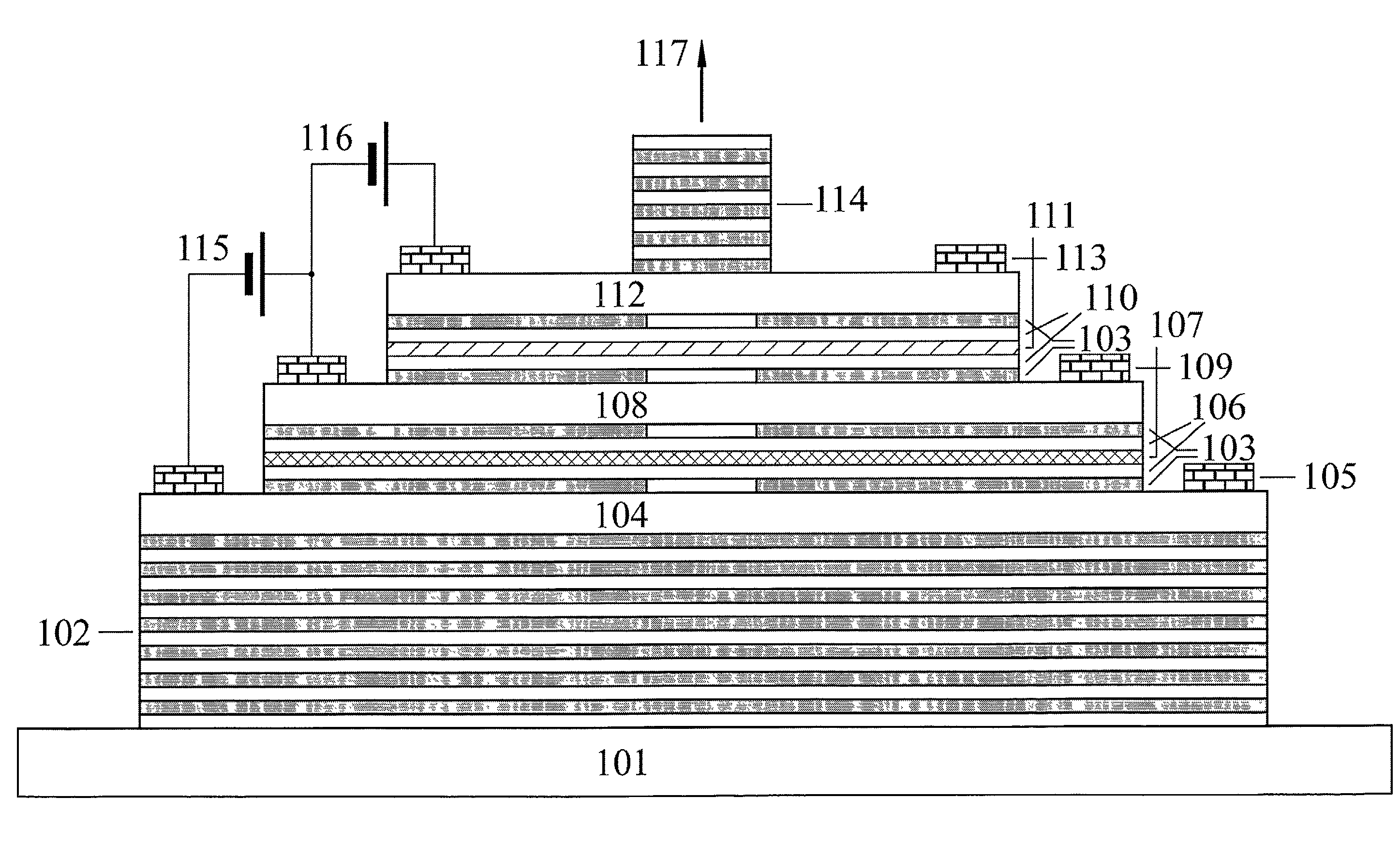
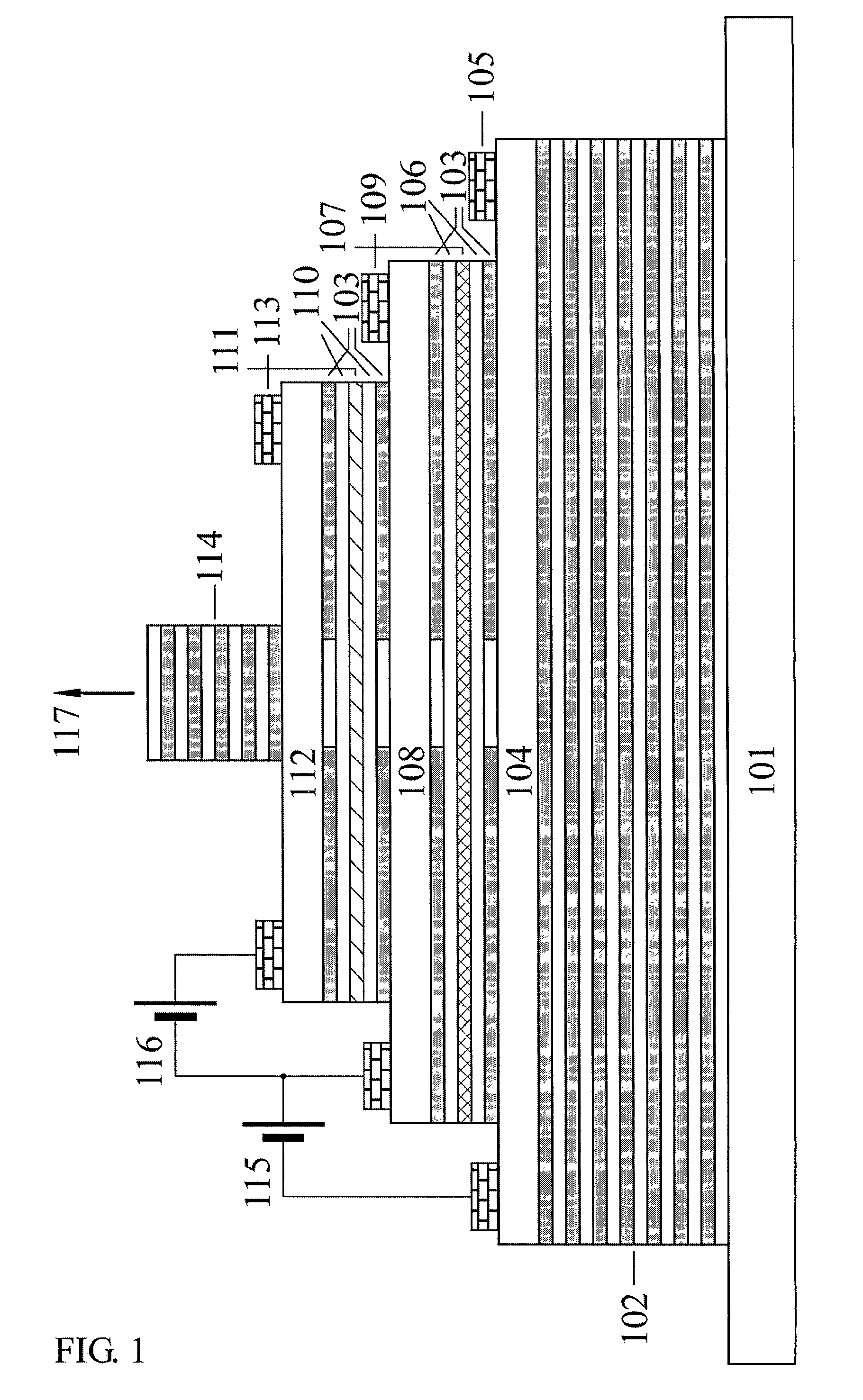
[0023] In a vertical cavity surface emitting laser (VCSEL), an active region is generally put into a microcavity. An undoped or weakly doped active region is surrounded by n-and p-contact layers that are generally followed by mirrors.

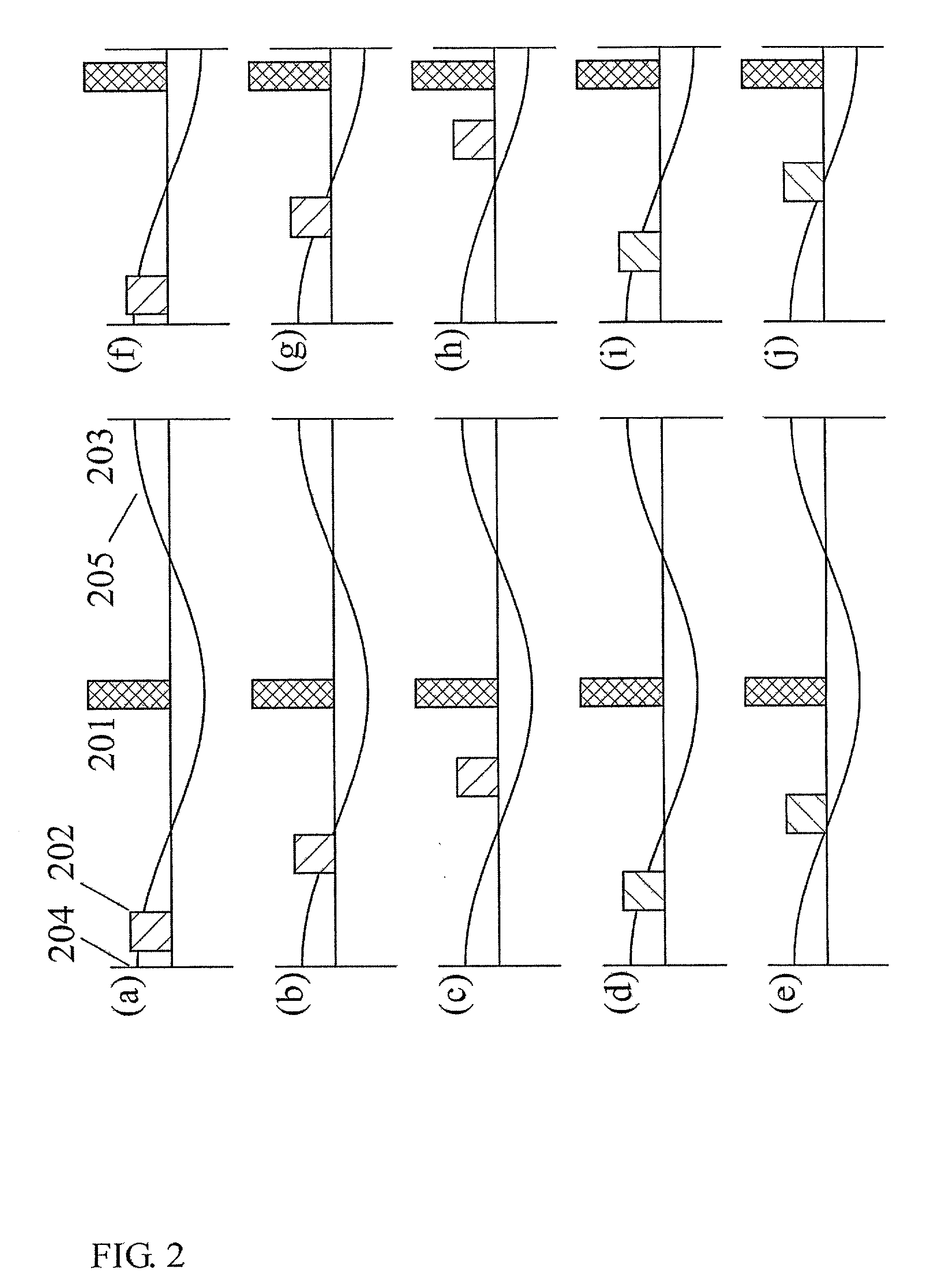
[0024] The present invention teaches adding a phase control element. The phase control element is a modulator surrounded on both sides by undoped or weakly doped layers which are in turn surrounded by n-and p-contact layers. An electric field is used to the tune the refractive index of the modulator.

[0025] Therefore, the tunable vertical cavity surface emitting laser of the present comprises two primary elements: 1) an active region and 2) a phase control element above the active region. These primary elements are sandwiched between two mirrors. The active element and the modulator are surrounded by undoped, or weakly doped, layers surrounded by n-and p-contact layers. Either electric fields or injection currents are used to control and tune the laser.

[...


PUM


Abstract

A wavelength tunable semiconductor vertical cavity surface emitting laser which includes at least one active element including an active layer generating an optical gain by injection of a current, and at least one phase control element, and mirrors. The phase control element contains a modulator exhibiting a strong narrow optical absorption peak on a short wavelength side from the wavelength of the laser generation. The wavelength control is realized by using a position-dependent electro-optical effect. If a reverse bias is applied, the absorption maximum is shifted to longer wavelengths due to the Stark effect. If a forward bias is applied, a current is injected and results in the bleaching and reduction of the peak absorption. In both cases a strong modulation of the refractive index in the phase control element occurs. The effect tunes the wavelength of the cavity mode, and the sign and the value of the wavelength shift are defined by the position of the modulator. Two phase control cascades can be implemented into the laser, one of which shifts the wavelength of the emitted light to larger values, and the other shifts the wavelength of the emitted light to smaller values. A power equalizing element can be used in such laser allowing either to maintain the constant output power at different emission wavelengths or to realize an independent frequency and amplitude modulation. A photodetecting element can be implemented in the laser allowing calibration of the laser for all operations.

Description

BACKGROUND OF THE INVENTION[0001] 1. Field of the Invention[0002] The invention pertains to the field of semiconductor devices. More particularly, the invention pertains to a wavelength tunable semiconductor vertical cavity surface emitting laser (VCSEL).[0003] 2. Description of Related Art[0004] The wavelength tunable semiconductor laser plays an important role in wavelength division multiplexing transmission systems, wavelength division switching systems, wavelength cross-connection systems as well as in the field of optical measurements.[0005] Prior art in this field includes far wavelength tunable edge-emitting lasers (M. Yamaguchi et al., U.S. Pat. No. 5,541,945) using different sections of the same waveguide structure of the device. Another way to achieve wavelength tunability for both edge-and surface emitting lasers is to use external mirrors or diffraction gratings, where the tuning is realized by mechanical tuning of the effective cavity length of the device (P. Tayebati, ...

Claims


Application Information

Patent Timeline
IPC IPC(8): H01S5/026H01S5/042H01S1/00H01S5/062H01S5/183H01S5/40
CPCH01S5/0264H01S5/06206H01S5/18341H01S5/1833H01S5/18302H01S5/183
Inventor LEDENTSOV, NIKOLAISHCHUKIN, VITALY
Owner INNOLUME
Why Eureka
Try Eureka