Co-based magnetic alloy and magnetic members made of the same
a magnetic alloy and co-based technology, applied in the direction of magnetic materials, basic electric elements, magnetic bodies, etc., can solve the problems of large noise generation, deterioration of magnetic properties under stress, and unsuitability of ferrite materials for high-power applications
- Summary
- Abstract
- Description
- Claims
- Application Information
AI Technical Summary
Problems solved by technology
Method used
Image
Examples
example 2
[0050] A molten alloy having a composition represented by the general formula (Co.sub.1-aFe.sub.a).sub.bal.Cu.sub.0.6Nb.sub.2.6Si.sub.9B.sub.9 (atomic %) was quenched in the single roll method to obtain a thin amorphous alloy strip having a width of 5 mm and thickness of 18 .mu.m. The thin amorphous alloy strip was wound into a toroidal magnetic core with an outer diameter of 19 mm and an inner diameter of 15 mm.
[0051] The magnetic alloy core was annealed in accordance with the same heat treatment pattern as that in Example 1, and magnetic properties of the core were measured. The heat-treated alloy were formed fine crystal grains having a grain size of not more than 50 nm. FIG. 4 shows Fe content (a) dependence of a saturation magnetic flux density B.sub.s, squareness ratio B.sub.r / B.sub.8000, and alternating-current relative initial permeability .mu..sub.riacat 1 kHz. FIG. 5 shows a dependence of an induced magnetic anisotropy constant K.sub.u on the Fe content (a). And FIG. 6 sho...
example 3
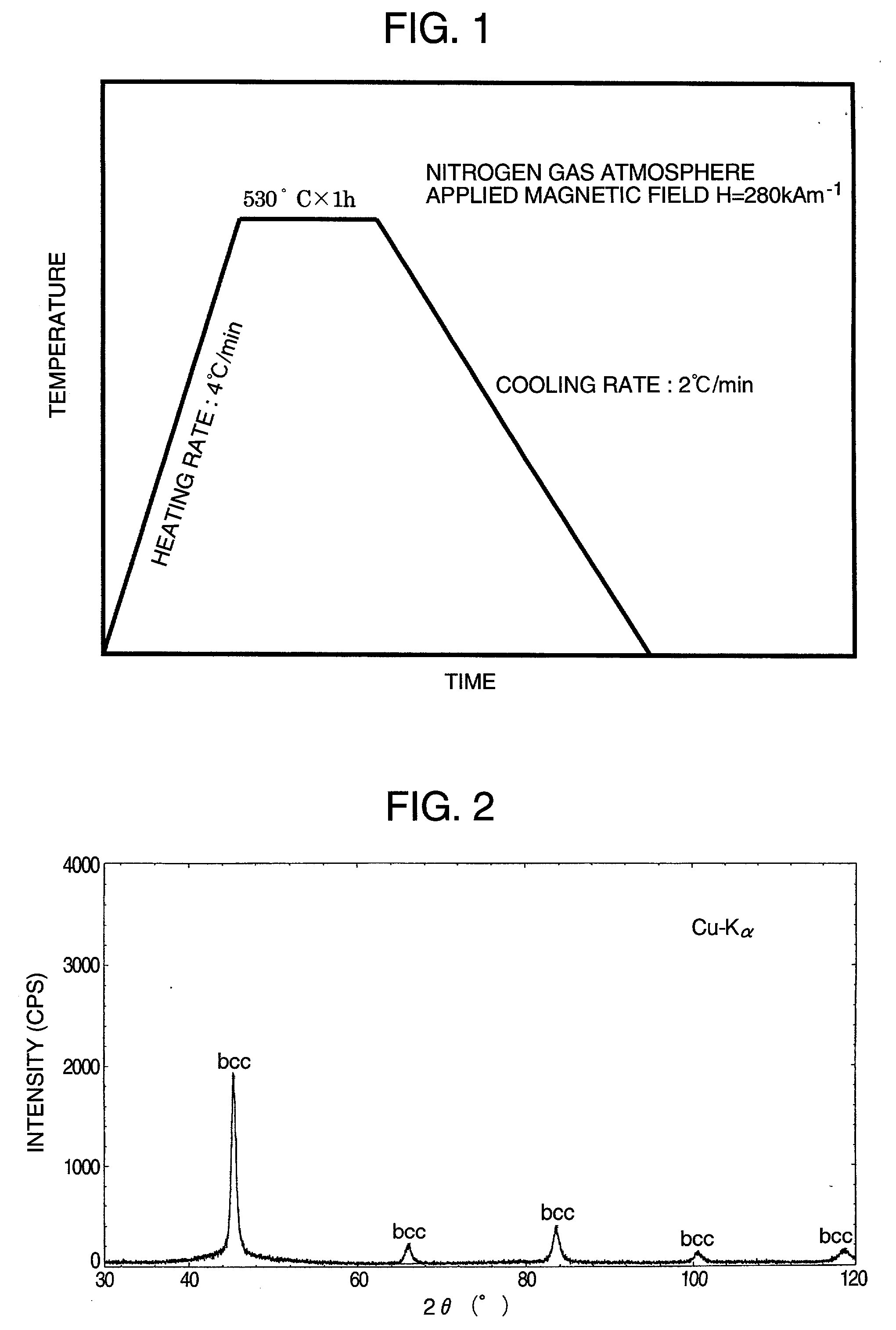
[0053] Molten alloys each having a chemical composition shown in Table 2 were rapidly quenched by the single roll method under the atmosphere or an Ar gas atmosphere to obtain thin amorphous alloy strips each having a width of 10 mm and thickness of 15 .mu.m. The alloys containing active metals such as Zr, Hf were fabricated under an Ar gas atmosphere. The thin amorphous alloy strips were wound into troidal magnetic cores having an outer diameter of 19 mm and an inner diameter of 15 mm. The magnetic alloy cores were subjected to heat treatment in accordance with the heat treatment pattern shown in FIG. 1. During the heat treatment, the magnetic field was applied in the direction perpendicular to the magnetic path of the magnetic core (in the width direction of the thin alloy strip). In the heat-treated alloys, there were formed extremely fine crystal grains having a grain size of not more than 50 nm and having a bcc phase, fcc phase, or hcp phase, respectively. With regard to the he...
example 4
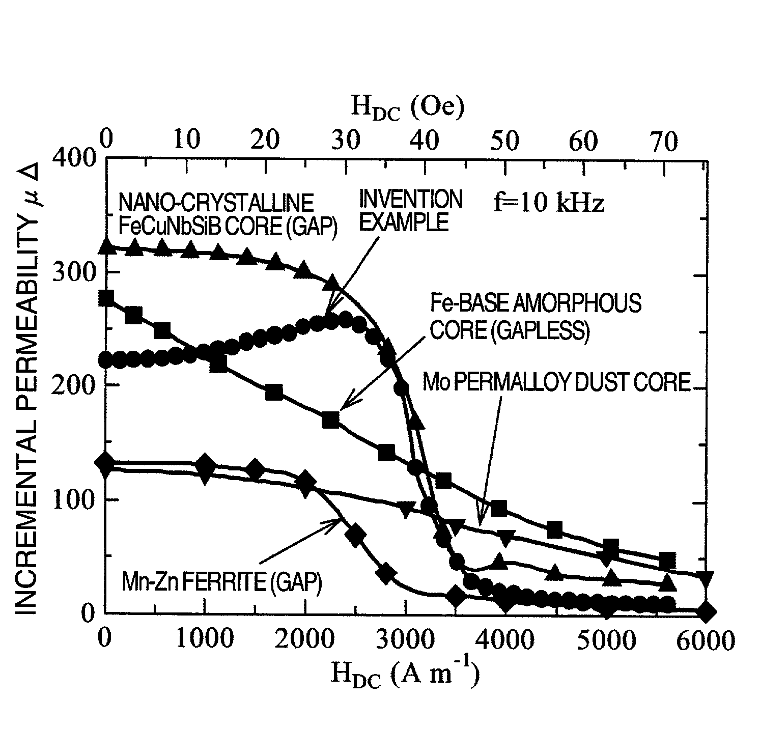
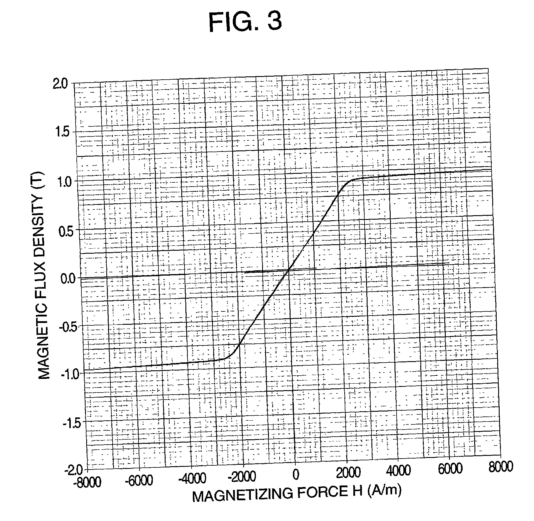
[0054] A molten alloy of (Co.sub.0.8Fe.sub.0.2).sub.bal.Cu.sub.1Nb.sub.3Si-.sub.13.5B.sub.9 (atomic %) was rapidly quenched in the single roll method to obtain a thin amorphous alloy strip having a width of 25 mm and thickness of 18 .mu.m. The thin amorphous alloy strip was wound into troidal magnetic cores having an outer diameter of 25 mm and an inner diameter of 20 mm. The magnetic field was applied in the height direction of the magnetic core (in the width direction of the thin alloy strip) and the magnetic alloy core was subjected to heat treatment in a magnetic field. The heat treatment was performed in accordance with the same heat-treatment pattern as that of Example 1, while the magnetic field was applied to the core through the period. It was confirmed by a transmission electron microscope and X-ray diffraction that there was formed crystal grains in the alloy, which have a grain size of 10 to 20 mm and body-centered cubic structure. According to a result of measurement of...
PUM
| Property | Measurement | Unit |
|---|---|---|
| Grain size | aaaaa | aaaaa |
| Percent by atom | aaaaa | aaaaa |
| Percent by atom | aaaaa | aaaaa |
Abstract
Description
Claims
Application Information
 - R&D
- Intellectual Property
- Life Sciences
- Materials
- Tech Scout
- Unparalleled Data Quality
- Higher Quality Content
- 60% Fewer Hallucinations
Browse by: Latest US Patents, China's latest patents, Technical Efficacy Thesaurus, Application Domain, Technology Topic, Popular Technical Reports.
© 2025 PatSnap. All rights reserved.Legal|Privacy policy|Modern Slavery Act Transparency Statement|Sitemap|About US| Contact US: help@patsnap.com


