Fractional-n frequency synthesizer

a synthesizer and n-frequency technology, applied in the direction of angle demodulation by phase difference detection, automatic control of pulses, electrical apparatus, etc., can solve the problem of conflict between two competing loops, difficulty in acquiring the correct frequency in the presence of jitter, and the output frequency of the acquired frequency (the output frequency of the vco) not being exactly the desired data signal frequency

Inactive Publication Date: 2003-01-09
2550 - ANALOG DEVICES
View PDF4 Cites 15 Cited by
  • Summary
  • Abstract
  • Description
  • Claims
  • Application Information

AI Technical Summary

Problems solved by technology

One drawback of this embodiment is that the received data signal is used as input to the FLL from which the clock signal is extracted and it may be difficult to acquire the correct frequency in the presence of jitter.
One drawback of this FLL design is that the frequency of the reference clock signal has an associated tolerance, therefore the acquired freq

Method used


Image

  • Fractional-n frequency synthesizer
  • Fractional-n frequency synthesizer
  • Fractional-n frequency synthesizer

Examples


Embodiment Construction

[0027] Definitions. As used in this description and the accompanying claims, the following terms shall have the meanings indicated, unless the context otherwise requires:

[0028] A cycle slip is detected as a transition across a quadrant boundary in a phasor diagram between the difference of two phasors wherein each phasor is representative of a signal. Such a transition occurs when one of the two signals acquires a full cycle of phase (2.pi. radians) more than the other signal.

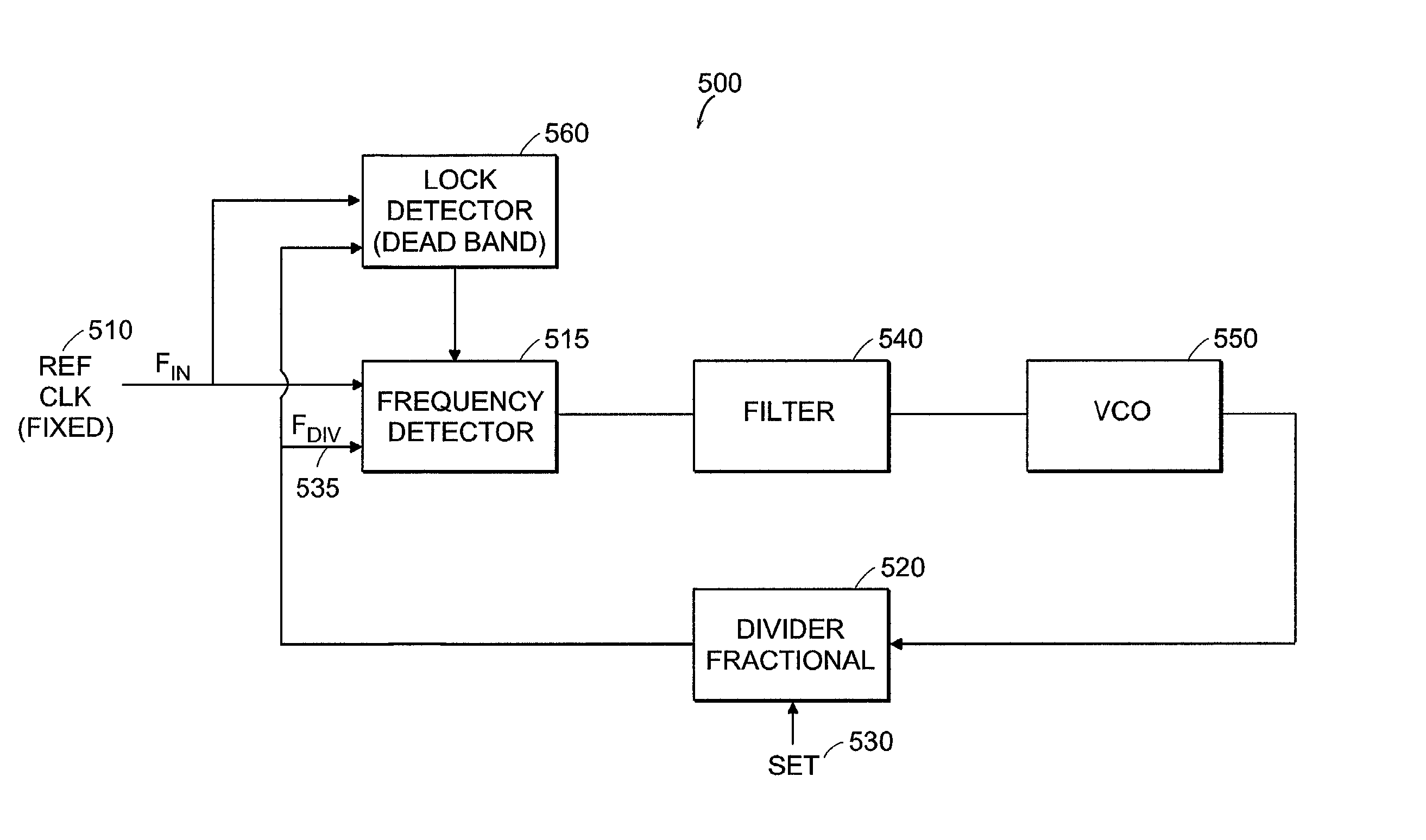
[0029] FIG. 5 is one embodiment for a frequency locked loop 500 for use in a clock and data recovery circuit. In this embodiment only a single fixed reference clock signal 510 is necessary to accommodate multiple received data rates. The frequency locked loop 500 includes a divider circuit 520, which is a fractional divider circuit. The fractional divider circuit 520 is capable of receiving an input control signal 530 which sets the divisor. Thus, multiple data rates can be accommodated with a single reference ...


PUM


Abstract

A frequency locked loop for providing an output signal having an output frequency within a predetermined range of a non-integer multiple of a reference frequency. The frequency locked loop includes a voltage element, such as a voltage controlled oscillator, which produces the output signal at the output frequency. The frequency locked loop further includes a fractional divider which is operably coupled to the voltage controlled oscillator. Further, the frequency locked loop includes a frequency detector, such as a rotational frequency detector, which is operably coupled to the fractional divider. The frequency detector receives the reference signal, such as a fixed clock signal, and the output of the fractional divider signal and outputs a frequency detector signal. In one embodiment, the rotational frequency detector responds to cycle slips of 2pi radians between the reference frequency and the output signal of the fractional divider. The frequency detector produces a signal which either increases or decreases charge on a capacitor which is read by the voltage element. The frequency locked loop may further incorporate a lock detector circuit for disabling the frequency detector when the output frequency is within the predetermined range.

Description

[0001] This application claims priority from U.S. Provisional Patent Application entitled Fractional-N Frequency Synthesizer having Serial No.: 60 / 301,563 and filed on Jun. 28, 2001.TECHNICAL FIELD AND BACKGROUND ART[0002] The present invention relates to frequency locked loops and more specifically to frequency locked loops in a clock and data recovery circuit.[0003] In telecommunication, clock extraction circuits are important components of electronic receivers. Normally when data is sent to a receiver, the received data signal needs to be synched with the local clock. Since a local clock is not available which has the correct phase and frequency as that of the received data signal, a clock and data recovery circuit is necessary. In a dock and data recovery circuit, a clock signal is extracted from the received signal and used to retime the data.[0004] FIG. 1, shows a prior art clock and data recovery circuit 100 which contains a phase locked loop (PLL) 110 and a frequency locked ...

Claims


Application Information

Patent Timeline
IPC IPC(8): H03L7/087H03L7/095H03L7/14H03L7/197
CPCH03L7/087H03L7/095H03L7/14H03L7/1974
Inventor DALTON, DECLAN M.DEVITO, LAWRENCE M.HITCHCOX, DAVID JOHNMURRAY, PAUL
Owner 2550 - ANALOG DEVICES
Why Eureka
Try Eureka