Flow meter type liquid filling apparatus

a liquid filling apparatus and flow meter technology, applied in liquid handling, packaging goods type, transportation and packaging, etc., can solve the problems of difficult to maintain the liquid pressure constant value, difficult to achieve an accurate measurement of the flow rate (injection amount) of liquid, and the inability to sharply detect the effect of the liquid

Inactive Publication Date: 2003-01-16
TOYO JIDOKI CO LTD
View PDF2 Cites 15 Cited by
  • Summary
  • Abstract
  • Description
  • Claims
  • Application Information

AI Technical Summary

Problems solved by technology

However, when the valves open or close, it is difficult to achieve an accurate measurement of the flow rate (injection amount) of the liquid flowing through the pipe channels, since the flow velocity is small and varies abruptly.
(1) Since the precision of the control of the air pressure in the reservoir tank by the pressurizing means is not very good (i.e., the air pressure inside the reservoir tank shows large fluctuations), it is difficult to maintain the liquid pressure at a constant value. Especially in the case of liquids that have a low viscosity, the liquid pressure used for filling must be set at a low value, so that the air pressure inside the reservoir tank must also be controlled to a low value. In such cases, however, control with good precision is achieved in a conventional apparatus.
(2) Even if the liquid pressure in the reservoir tank or in the liquid pipe channel adjacent to the reservoir tank is maintained at a constant value, the liquid pressure in the vicinity of the filling nozzles may not be constant. More specifically, the pressure loss caused by the resistance of the piping extending from the installation position of the liquid pressure sensor (i.e., the liquid pressure measurement position) to the filling nozzles increases with an increase in the viscosity of the liquid; and if the temperature of the liquid varies or the air temperature varies (e.g., between morning and noontime) so that the viscosity of the liquid varies, then the liquid pressure in the vicinity of the filling nozzles will fluctuate even in cases where the liquid pressure sensor shows the same liquid pressure.
(3) There are also problems in the detection precision itself of the liquid pressure detected by the liquid pressure sensor. In other words, in cases where the valves of a plurality of filling nozzles are successively opened and closed, an abnormal pressure is outputted as a result of the phenomenon of water hammer when the valves are closed. Furthermore, air contained in the liquid may remain in the position of the liquid pressure sensor, so that sharp accurate detection becomes impossible because of the compressibility of air.

Method used


Image

  • Flow meter type liquid filling apparatus
  • Flow meter type liquid filling apparatus
  • Flow meter type liquid filling apparatus

Examples


Embodiment Construction

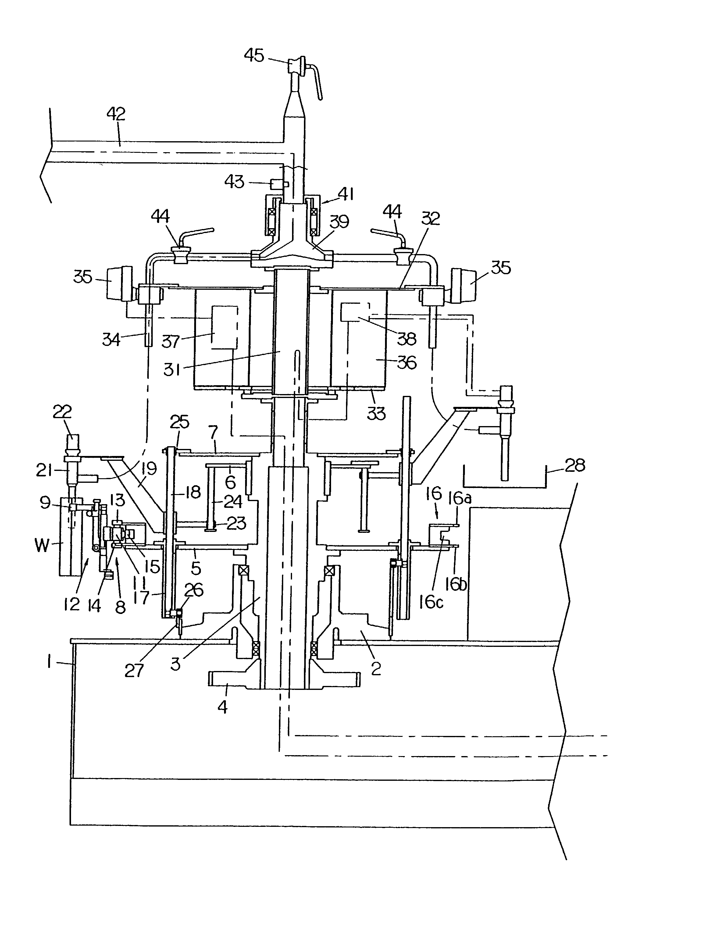
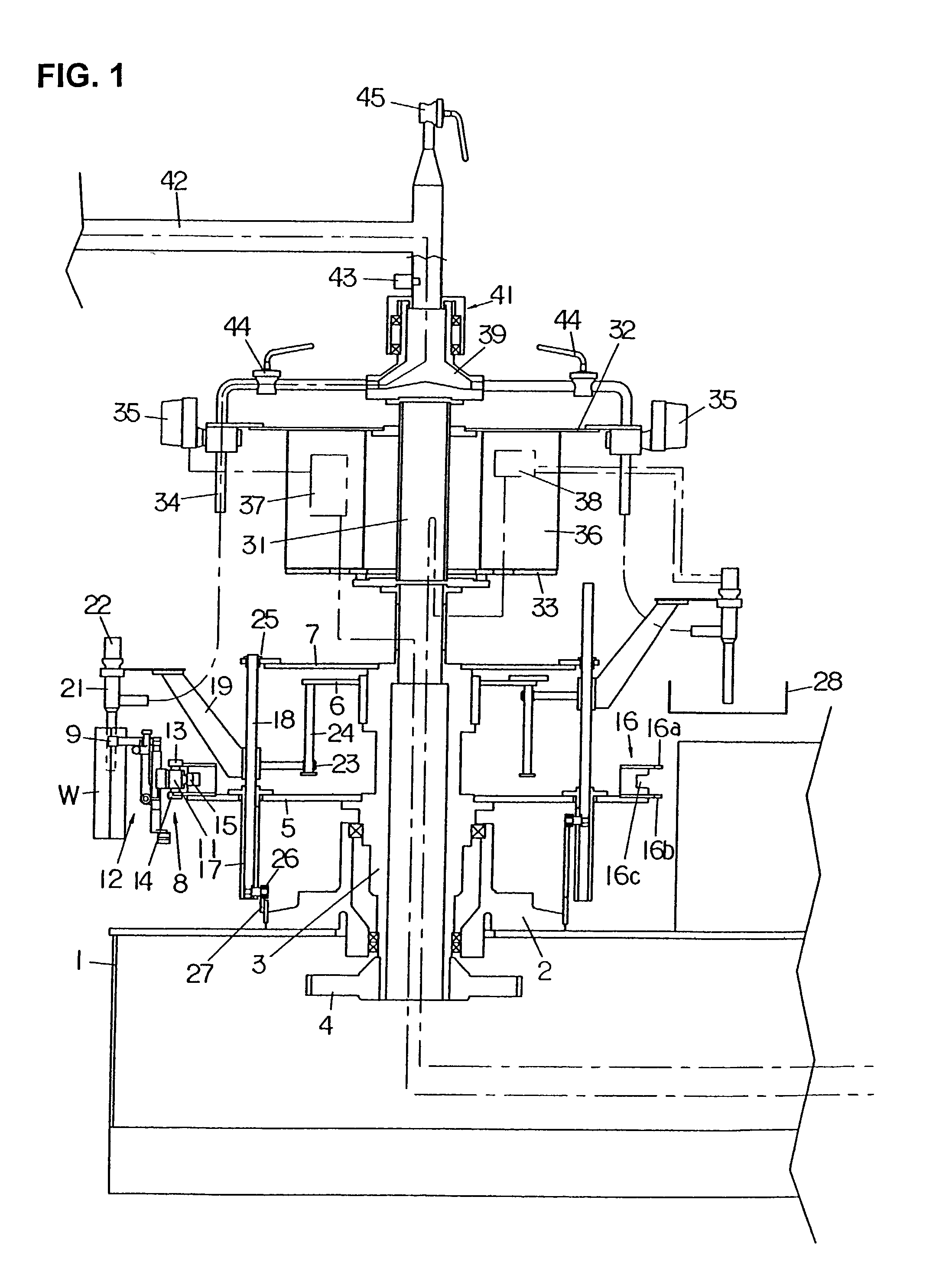
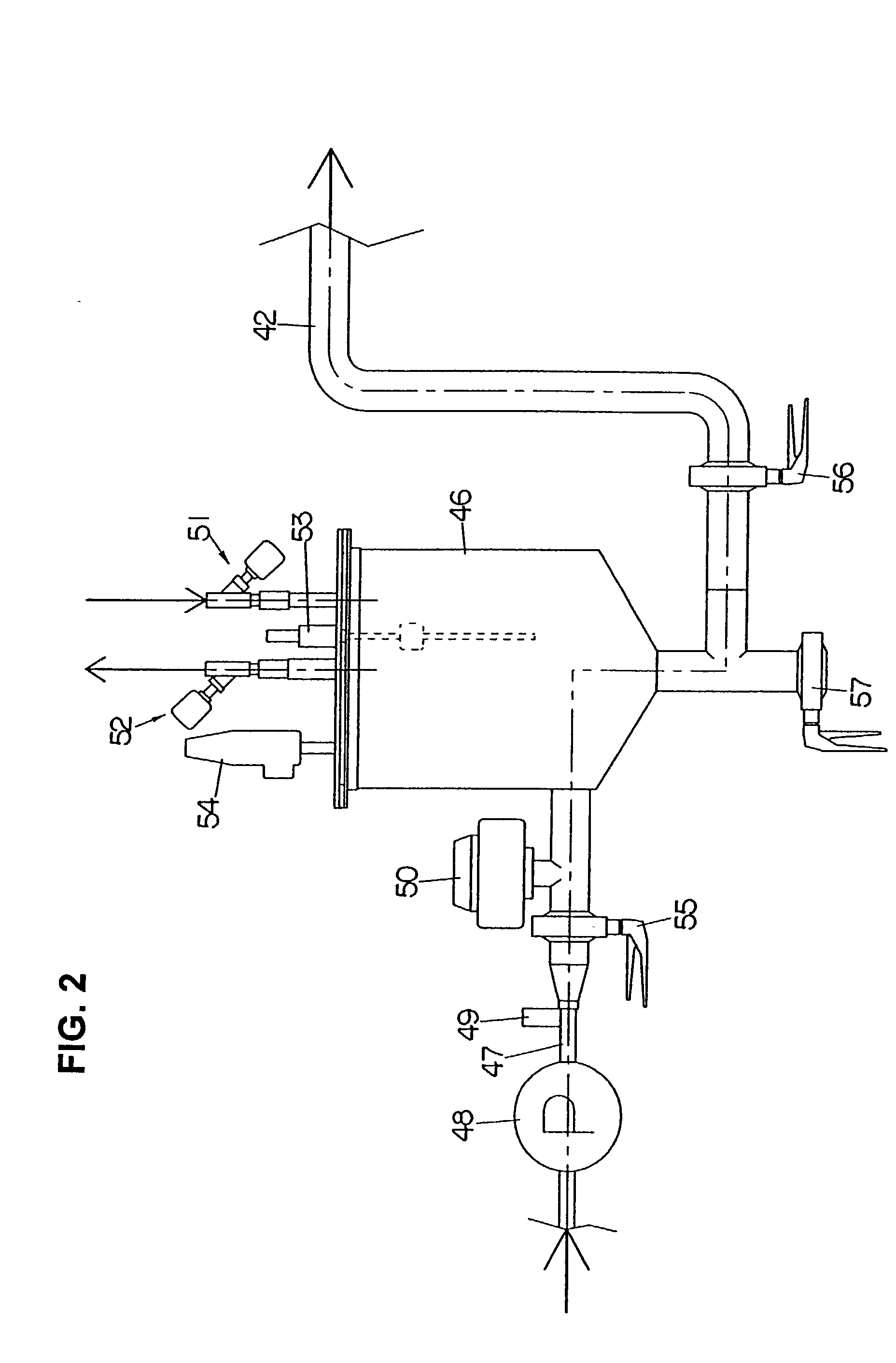
[0068] The flow meter type liquid filling apparatus of the present invention will be concretely described below with reference to FIGS. 1 through 4.

[0069] The nozzle assembly of this flow meter type liquid filling apparatus is a rotary type. As shown in FIG. 1, a stand 2 is installed in an upright attitude on a base 1, and a hollow rotary shaft 3 is ratably supported on this stand 2. The hollow rotary shaft 3 is caused to rotate continuously by a driving means (not shown) via a gear 4 fastened to the lower end of the hollow rotary shaft 3.

[0070] A sprocket 5 and rotating tables 6 and 7 are fastened to the circumference of the hollow rotary shaft 3.

[0071] One end of an endless chain 8 is mounted on the sprocket 5, and a plurality of gripper pairs 9 that hold both edges of bags (containers) W are attached to this endless chain 8 at equal intervals. The gripper pairs 9 are thus moved along a horizontal racetrack-form path as the hollow rotary shaft 3 and sprocket 5 rotate. The endless ...


PUM

PropertyMeasurementUnit
pressureaaaaaaaaaa
air pressureaaaaaaaaaa
flow rateaaaaaaaaaa

Abstract

A rotary and flow meter type liquid filling apparatus including a liquid reservoir tank that stores and supplies liquid to filling nozzles, and air supply paths for different amount of air supply and air discharge paths for different amount of air discharge being connected to the liquid reservoir tank. An air compressor is connected to the air supply paths, and the air discharge paths open into the atmosphere. A liquid pressure sensor disposed near the filling nozzles sense the increase or decrease of the liquid pressure inside a pipe that connects the liquid reservoir tank and liquid filling nozzles, and the electromagnetic valves provided on the air supply and air discharge paths are opened or closed, thus supplying air to and discharging air from the liquid reservoir tank so as to control the air pressure inside the liquid reservoir tank and the liquid pressure near the liquid filling nozzles.

Description

[0001] 1. Field of the Invention[0002] The invention relates to a liquid filling apparatus and more particularly to an improvement in an apparatus that fills containers with liquid and is provided with liquid flow meters.[0003] 2. Prior Art[0004] Liquid filling apparatuses that fill containers with liquid have been known, and one type thereof is a flow meter type liquid filling apparatus.[0005] A typical flow type liquid filling apparatus includes a plurality of filling nozzles that have feed-out openings and opening-and-closing valves, valve actuating means which are installed at positions that correspond to the respective filling nozzles and which open and close the valves of the respective filling nozzles, a reservoir tank which stores a liquid, a liquid supplying means which is connected to the upstream side of the reservoir tank, an air pressure adjustment means which adjusts the air pressure inside the reservoir tank, liquid pipe channels which branch from the reservoir tank v...

Claims


Application Information

Patent Timeline
Patent Type & Authority Applications(United States)
IPC IPC(8): B67C3/28B67C3/00
CPCB67C3/007
Inventor TANAKA, NAMIYOSHIOKAZAKI, HIROYUKIKOGA, SHOICHI
Owner TOYO JIDOKI CO LTD
Why Eureka
Try Eureka