Monolithic ceramic laser structure and method of making same

a monolithic ceramic and laser technology, applied in the field of gas laser technology, can solve the problems of inability to mass produce a laser with consistency, inability to protect the laser from mechanical as well as thermal shock, and often prove impractical to cool the laser without water, etc., and achieve the effect of reducing the cost of production

Inactive Publication Date: 2003-01-16
MORROW CLIFFORD E
View PDF20 Cites 27 Cited by
  • Summary
  • Abstract
  • Description
  • Claims
  • Application Information

AI Technical Summary

Problems solved by technology

When considering glass, the ability to mass produce a laser with consistency, cool it without the use of water and protect it from mechanical as well as thermal shock often proves impractical.
Metal lasers, as for example the design described in U.S. Pat. No. 5,953,360, are most often made of aluminum, suffer from complexity, as many components need to be installed inside the metal enclosure "ship-in-a-bottle" style adding cost and reducing consistency unit to unit.
Aluminum lasers also require adjustable mirror mounts that are often prone to misalignment over time.
Heat extraction from these lasers tends to be asymmetrical causing a slight warp resulting in cavity mirror misalignment.
Feed through can present a reliability issue and add cost.
Although this assembly was intended to produce a HeNe ring laser gyroscope, the concept of building a laser from plates can be applied to the CO.sub.2 laser, however with different materials since quartz and Cer-Vit don't allow the efficient removal of heat needed for the CO.sub.2 laser.
The heating and kiln support requirements to subsequently fuse the alumina plates together will now be higher than in the polished case, however, the cost of this process will be much lower than if the laser halves would need to be polished and very flat over a large area.
If this high temperature fusing method is used, the ceramic assembly will warp and create a subsequent yield issue.

Method used


Image

  • Monolithic ceramic laser structure and method of making same
  • Monolithic ceramic laser structure and method of making same
  • Monolithic ceramic laser structure and method of making same

Examples


Embodiment Construction

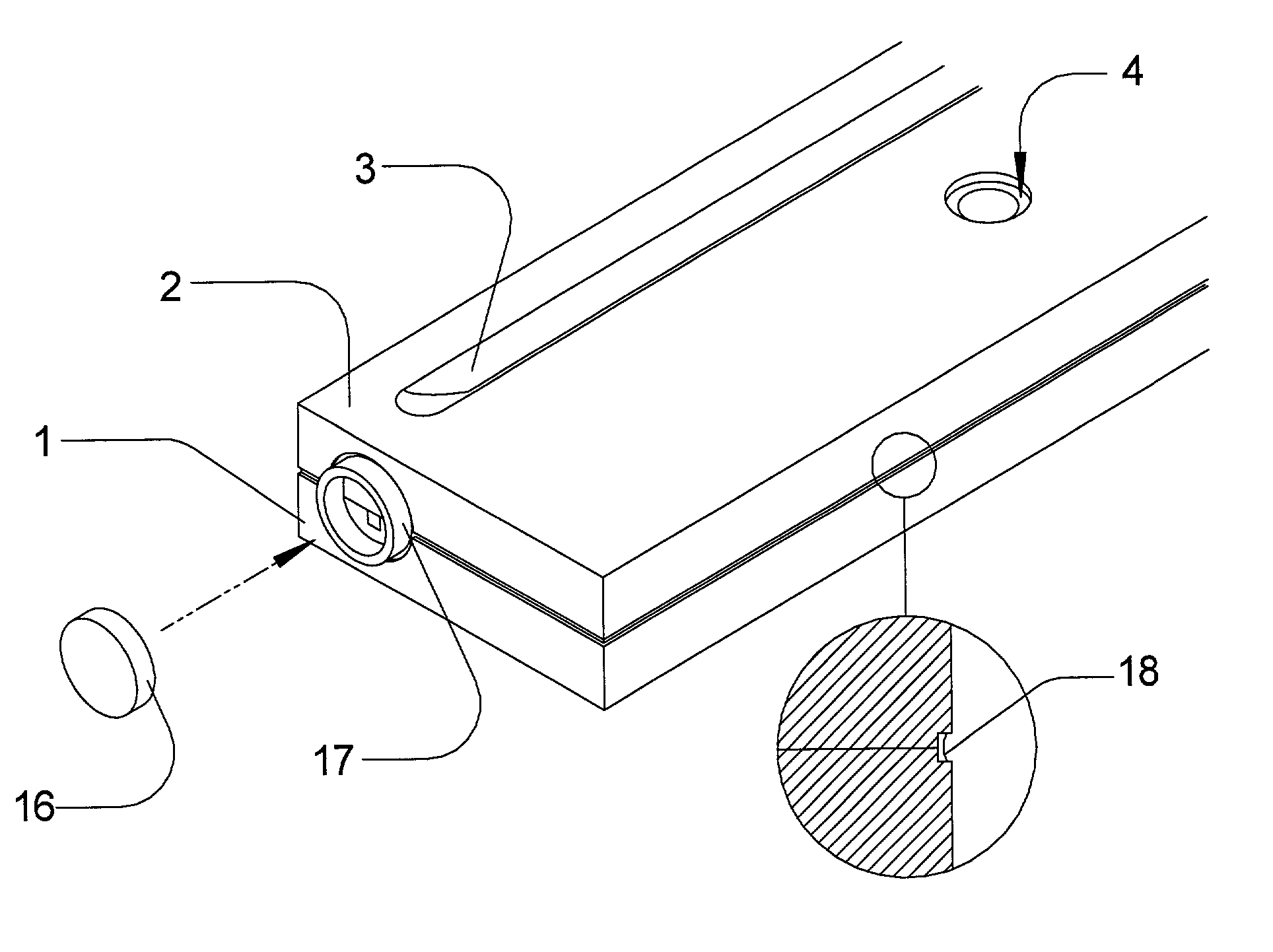
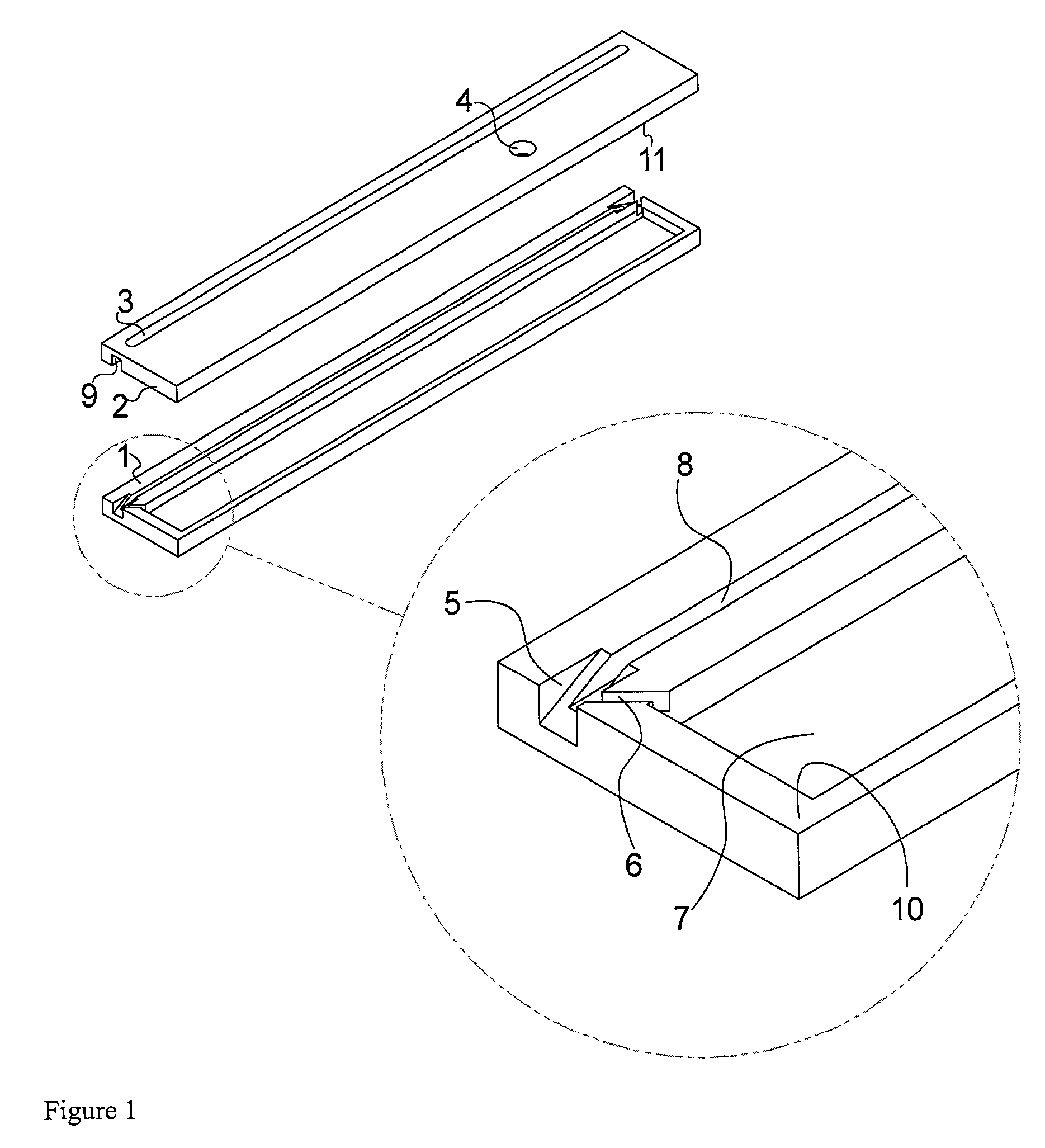
[0036] FIG. 1, shows one embodiment of an RF excited laser body assembled from two halves of alumina ceramic 1,2. The lower half is prepared with internal features 5,6,7,8 which can be accomplished by using a surface grinder. Feature 6 is the gas communication channel between the waveguide bore, 8 and the reservoir, 7. The gas communication channel may be angled in such a way as to allow an uninterrupted grinding path from the interior of the reservoir through to the waveguide setback region 5.

[0037] The waveguide setback slot 5 suppresses potential higher order modes from oscillating between the resonator mirrors (not shown). The setback slot 5 may be created by use of a reciprocating surface grinder set to an angle to produce the desired setback and avoid retro reflections from occurring. In particular, in the example shown in FIG. 1 the angle of this slot 5 is not 45.degree. so as to avoid the condition of retroreflection which can result in unintended modes being present within ...


PUM

PropertyMeasurementUnit
surface roughnessaaaaaaaaaa
angleaaaaaaaaaa

Abstract

A monolithic ceramic waveguide laser body is made by forming and grinding two or more plates of alumina ceramic to produce internal and external features otherwise impossible to fabricate in a single ceramic body. The plates are bonded together by use of glass frit or by self-friting (diffusion bonding) methods to achieve a vacuum tight enclosure. The ceramic surfaces to be bonded have an "as ground" finish. One internal structure created by this method includes a channel of dimensions from 8 to 1.5 mm square or round that confines an RF or DC electrical discharge and comprises a laser resonator cavity. The channel can be ground to form a "V", "U" or "Z" shape folded cavity. Another internal structure is a gas reservoir connected to the resonator cavity. Various other important features are described that can only be created by this method of building a laser. The plates are bonded together in a furnace at temperatures ranging between 450° C. and 1700° C., depending on the method used.

Description

RELATED APPLICATIONS AND CLAIM OF PRIORITY[0001] This application claims the benefit of and incorporates in its entirety herein by reference the contents of the following co-pending applications: Application No. 60 / 277,025 filed Mar. 19, 2001, entitled "Method of Making a Monolithic Ceramic CO2 Laser Structure" and: Application No. 60 / 350,638 filed Jan. 23, 2002, entitled "Monolithic Ceramic Laser Structure and Method of Making Same".BACKGROUND OF INVENTION[0002] 1. Field of Invention[0003] This invention relates to gas laser technology and in particular to gas lasers constructed of ceramic materials such as Alumina and Beryllia.[0004] 2. Description of Prior Art[0005] It is well known that laser cavity structures can be made of a variety of materials as long as vacuum integrity, electrical requirements and dimensional stability are satisfied.[0006] Lasers of aluminum and glass are most common because of the relative ease of forming and machining these materials into the required co...

Claims


Application Information

Patent Timeline
Patent Type & Authority Applications(United States)
IPC IPC(8): H01S3/03H01S3/034H01S3/081H01S3/22H01S3/223
CPCH01S3/0305H01S3/034H01S3/0813Y10T156/1064H01S3/0816H01S3/2222H01S3/2232H01S3/0815
Inventor MORROW, CLIFFORD E.
Owner MORROW CLIFFORD E
Why Eureka
Try Eureka