Liquid crystal driving devices

a driving device and liquid crystal technology, applied in the direction of instruments, computing, electric digital data processing, etc., can solve the problems of poor display quality, short time, flicker in the display of tones, etc., and achieve the effect of low production cos

Inactive Publication Date: 2003-01-16
SHARP KK
View PDF4 Cites 30 Cited by
  • Summary
  • Abstract
  • Description
  • Claims
  • Application Information

AI Technical Summary

Benefits of technology

0026] An object of the present invention is to provide liquid crystal driving devices that require low production cost for various types of liquid crystal display devices, by enabling a single driving IC to be shared between liquid crystal display devices that display high-quality and multi-tone images and liquid crystal display devices that do not require many tones.

Problems solved by technology

Thus, when the liquid crystal panel 1003 is used to carry out large-screen or high-resolution display by the frame rate control method or pulse modulation method, flicker is caused in a display of tones with a short ON time and a poor display quality results.
The dual-scan display mode, compared with the single-scan display mode, requires two driving circuits for the upper part and lower part of the liquid crystal panel, and therefore increases the scale of LSI mounting and the complexity of the driving circuits.
However, an increase of display memory capacity is generally associated with an increase in unit cost of the driver, which increases production cost of the liquid crystal display device.
Also, display panels with a small number of tones, because of their low unit sale price, cannot generally afford expensive drivers with a large memory capacity for displaying multi tones.
This is disadvantageous in terms of reducing cost by mass-production.
As a result, a high production cost is borne for the liquid crystal display device.

Method used


Image

  • Liquid crystal driving devices
  • Liquid crystal driving devices
  • Liquid crystal driving devices

Examples


first embodiment

[0059] [First Embodiment]

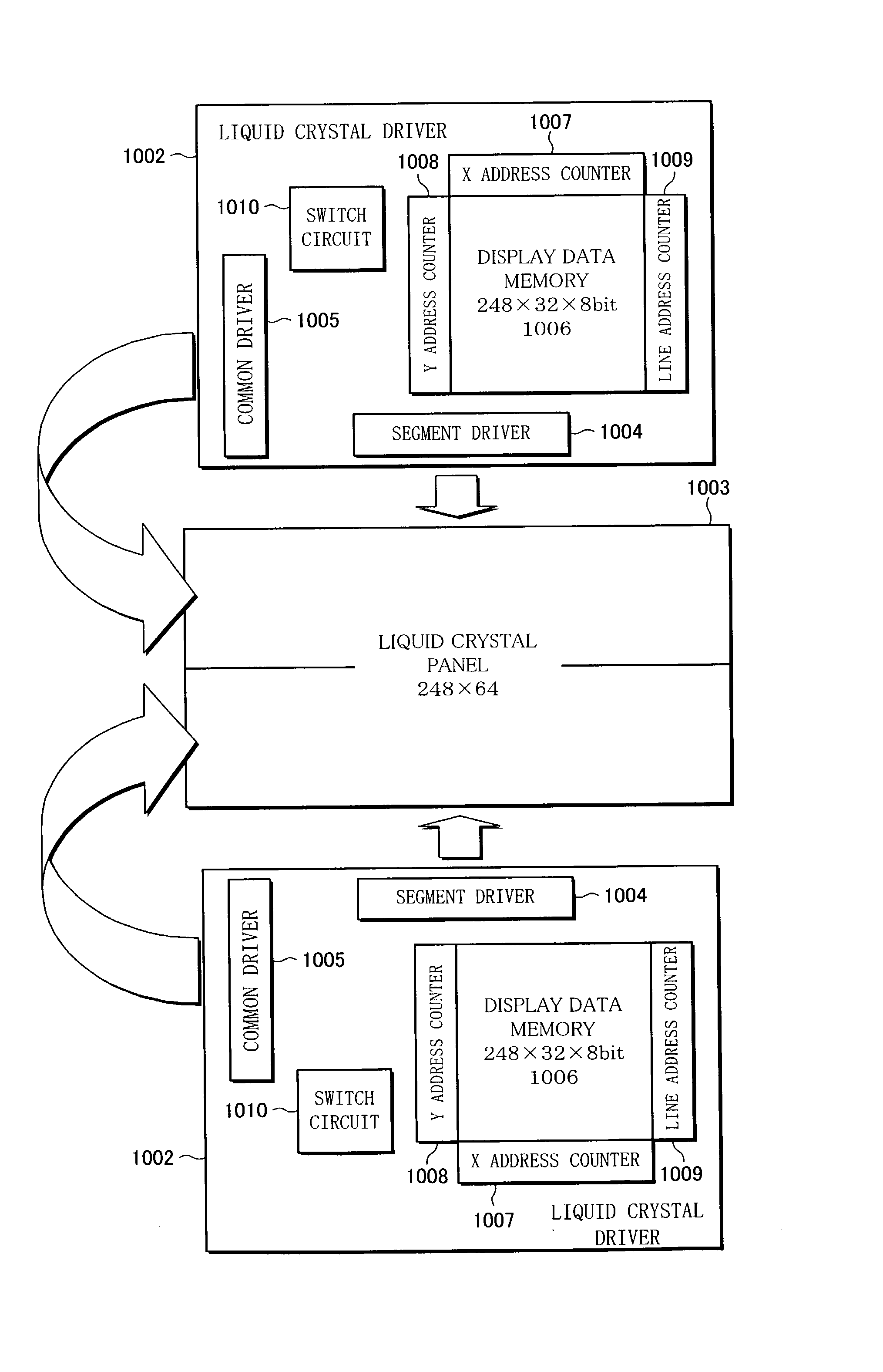
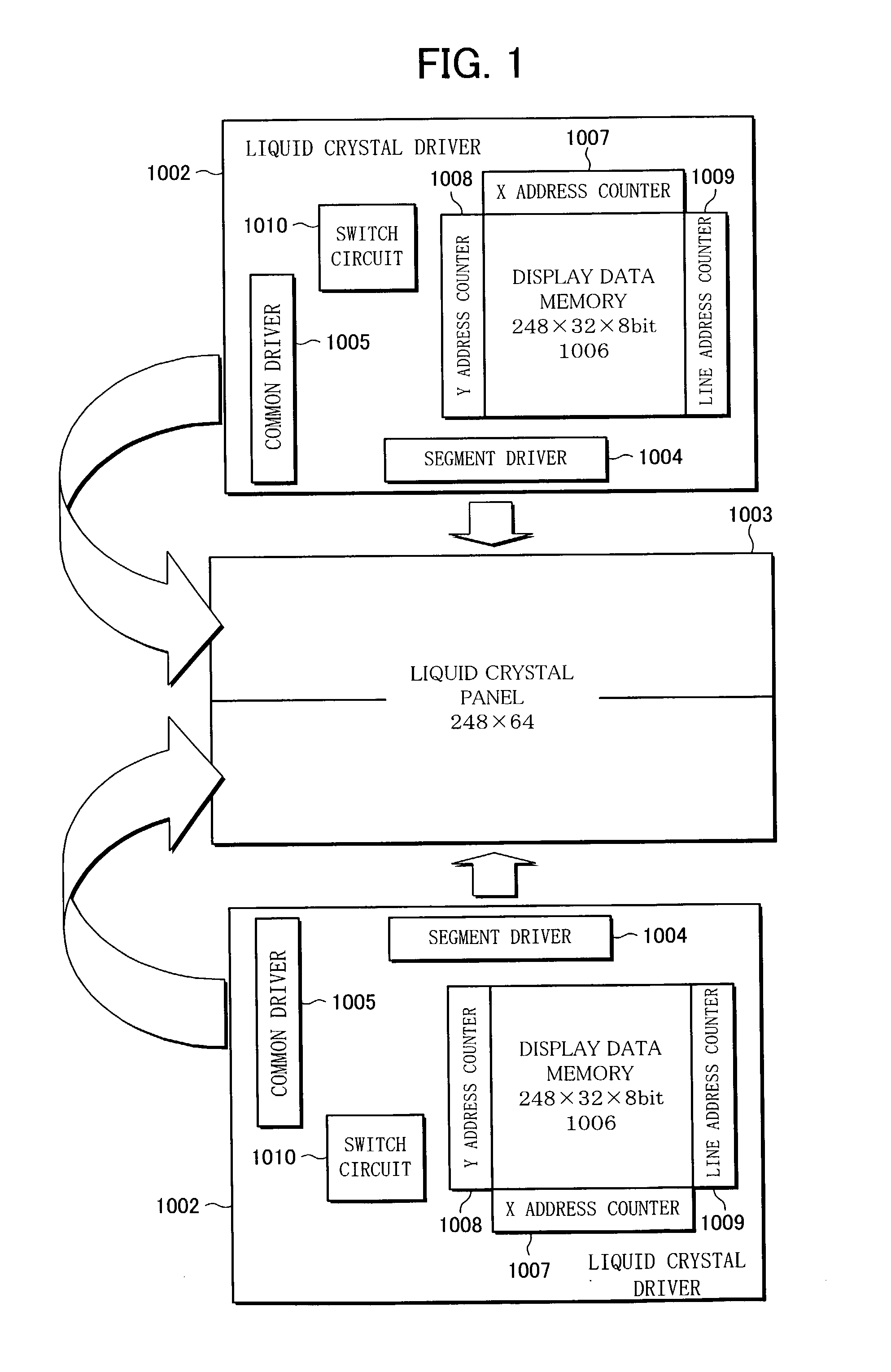
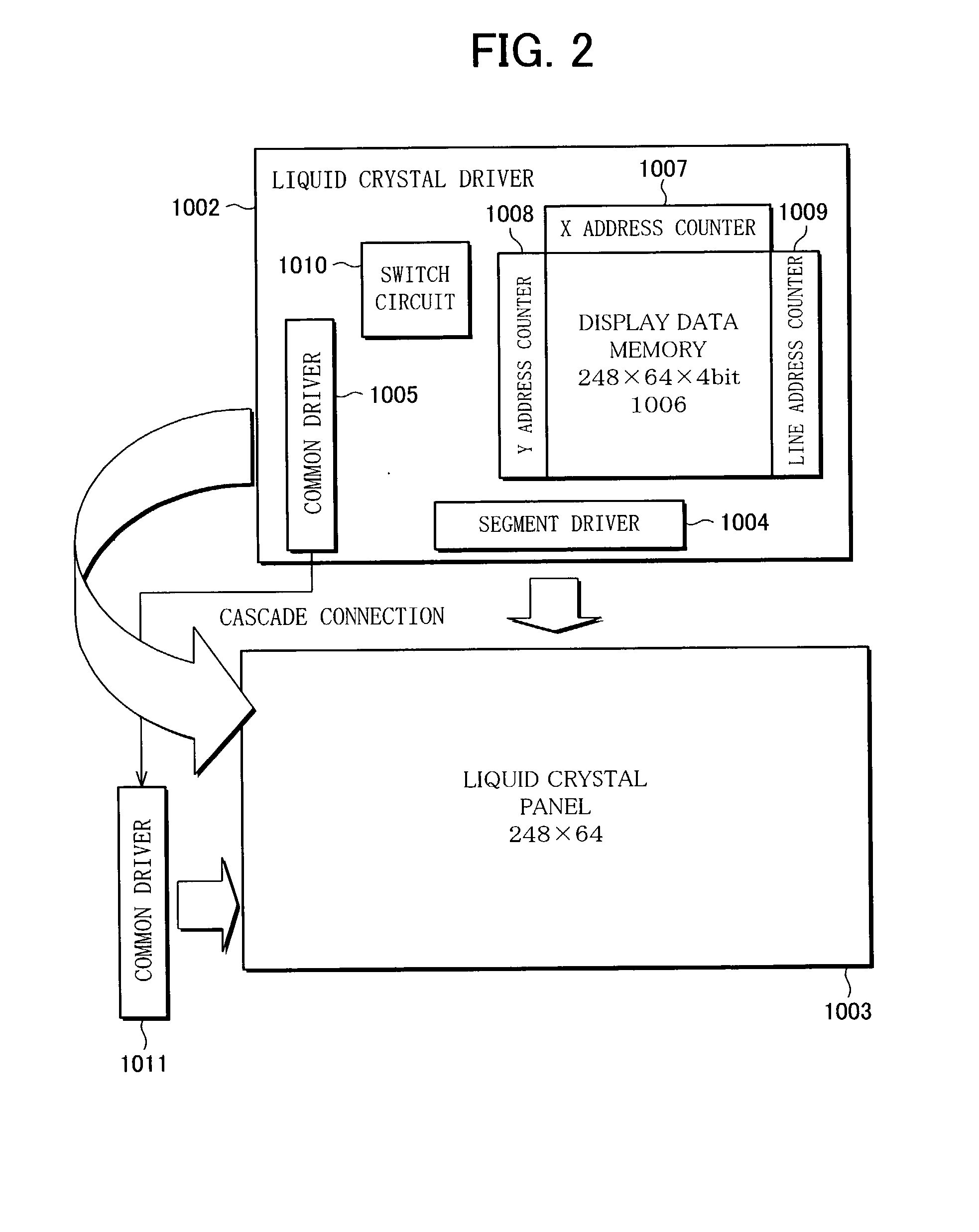
[0060] The following will describe one embodiment of the present invention. FIG. 1 of the embodiment illustrates a liquid crystal display device of a dual-scan display mode, and FIG. 2 of the embodiment illustrates a liquid crystal display device of a single-scan display mode.

[0061] First, referring of FIG. 1, the liquid crystal display device of the dual-scan display mode is described below.

[0062] A liquid crystal panel 1003 shown in FIG. 1 is a matrix-type STN liquid crystal display panel with 248 segment lines and 64 common lines, capable of displaying 2.sup.k tones (k is a natural number). In the dual-scan display mode, the number of tones is 256 and therefore k=8.

[0063] A liquid crystal driver (liquid crystal driving device) 1002 is a single-chip LSI that is realized by: a common driver (row driver) 1005 with n (n is a natural number) outputs for driving 32 lines; a segment driver (column driver) 1004 with m (m is a natural number) outputs for driving 2...

second embodiment

[0080] [Second Embodiment]

[0081] The following will describe another embodiment of the present invention. FIG. 3 of the embodiment illustrates a liquid crystal display device of the dual-scan display mode, and FIG. 4 of the embodiment illustrates a liquid crystal display device of the single-scan display mode.

[0082] In the present embodiment, as shown in FIG. 4, the single-scan display mode employs an externally-provided output select circuit (output number converter circuit) 1012 of 32 inputs and 64 outputs, so as to enable a liquid crystal driver 1002 to adapt to both the dual-scan display mode and the single-scan display mode.

[0083] The switch circuit 1010 of the First Embodiment is replaced with a select circuit 1110 in the present embodiment.

[0084] The select circuit 1110, in addition to the function of the switch circuit 1010, has a function of outputting a switch signal S which switches between the first half (line 1 through line 32) and the second half (line 33 through line ...

third embodiment

[0100] [Third Embodiment]

[0101] The following will describe yet another embodiment of the present invention. FIG. 6 of the embodiment illustrates a liquid crystal display device of the dual-scan display mode, and FIG. 7 of the embodiment illustrates a liquid crystal display device of the single-scan display mode.

[0102] The present embodiment describes a liquid crystal driving device that is provided with a common driver, that has adapted to the single-scan display mode, for driving 64 lines, and an internal counter, provided in the switch circuit 1010, for switching between 32 lines and 64 lines.

[0103] Accordingly, the common driver has shift registers of 64 stages. In the single-scan display mode, the start pulse signal is transferred through all the 64 stages and the scanning signal is created based on the output of each shift register stage so as to accommodate 64 lines.

[0104] On the other hand, in the dual-scan display mode, the shift registers stop outputting at the 32nd stage....


PUM

PropertyMeasurementUnit
power consumptionaaaaaaaaaa
poweraaaaaaaaaa
voltage average methodaaaaaaaaaa

Abstract

A liquid crystal driving device of the present invention is provided with a display data memory of a capacity that can be divided into two parts, and a switch circuit that is used to switch an addressing method of the display data memory between multi-tone display in a dual-scan and simple-tone display in a single-scan, so as to enable a driving IC to be shared between liquid crystal display devices that are used to display high-quality and multi-tone images and liquid crystal display devices that require less tone. Such a liquid crystal driving device can be used to reduce production cost of various types of liquid crystal display devices.

Description

FIELD OF THE INVENTION[0001] The present invention relates to liquid crystal driving devices for driving matrix-type liquid crystal display panels having a tone display capability.BACKGROUND OF THE INVENTION[0002] Conventionally, there have been proposed various techniques for reducing power consumption of liquid crystal display devices. For example, Japanese Publication for Unexamined Patent Application No. 281933 / 1997 (Tokukaihei 9-281933) (published on Oct. 31, 1997) discloses a technique in which a display memory is installed in a driver LSI of the liquid crystal panel to limit external access to the display memory when displaying a still image in particular, so that the power consumption of the liquid crystal display device can be reduced.[0003] Such a liquid crystal display device is described below with reference to FIG. 10. It is assumed here that a liquid crystal panel 1003 is used in a matrix-type liquid crystal display device and is AC-driven according to a line-sequentia...

Claims


Application Information

Patent Timeline
Patent Type & Authority Applications(United States)
IPC IPC(8): G02F1/133G09G3/20G09G3/36
CPCG09G3/2014G09G3/2025G09G2330/021G09G3/3681G09G3/3692G09G3/3644G02F1/133
Inventor MURAHASHI, SHUNICHIKATSUTANI, MASAFUMI
Owner SHARP KK
Why Eureka
Try Eureka