
Folded image intensifier objective lens

Inactive Publication Date: 2003-01-16
UNITED STATES OF AMERICA THE AS REPRESENTED BY THE SEC OF THE ARMY
View PDF0 Cites 7 Cited by
  • Summary
  • Abstract
  • Description
  • Claims
  • Application Information

AI Technical Summary

Problems solved by technology

Typical intensification devices have objective lenses with F#'s ranging from 1.0 to 1.5, the limitation most often being that lenses with lower F#'s are difficult to design and impractical to fabricate.
In these cases, the packaging requirements may impose restrictions on the sensor layout.
While the prior art has reported using optical assemblies for image intensifiers none have established a basis for a specific optical assembly that is dedicated to the task of resolving the particular problem at hand.

Method used


Image

  • Folded image intensifier objective lens
  • Folded image intensifier objective lens
  • Folded image intensifier objective lens

Examples


Embodiment Construction

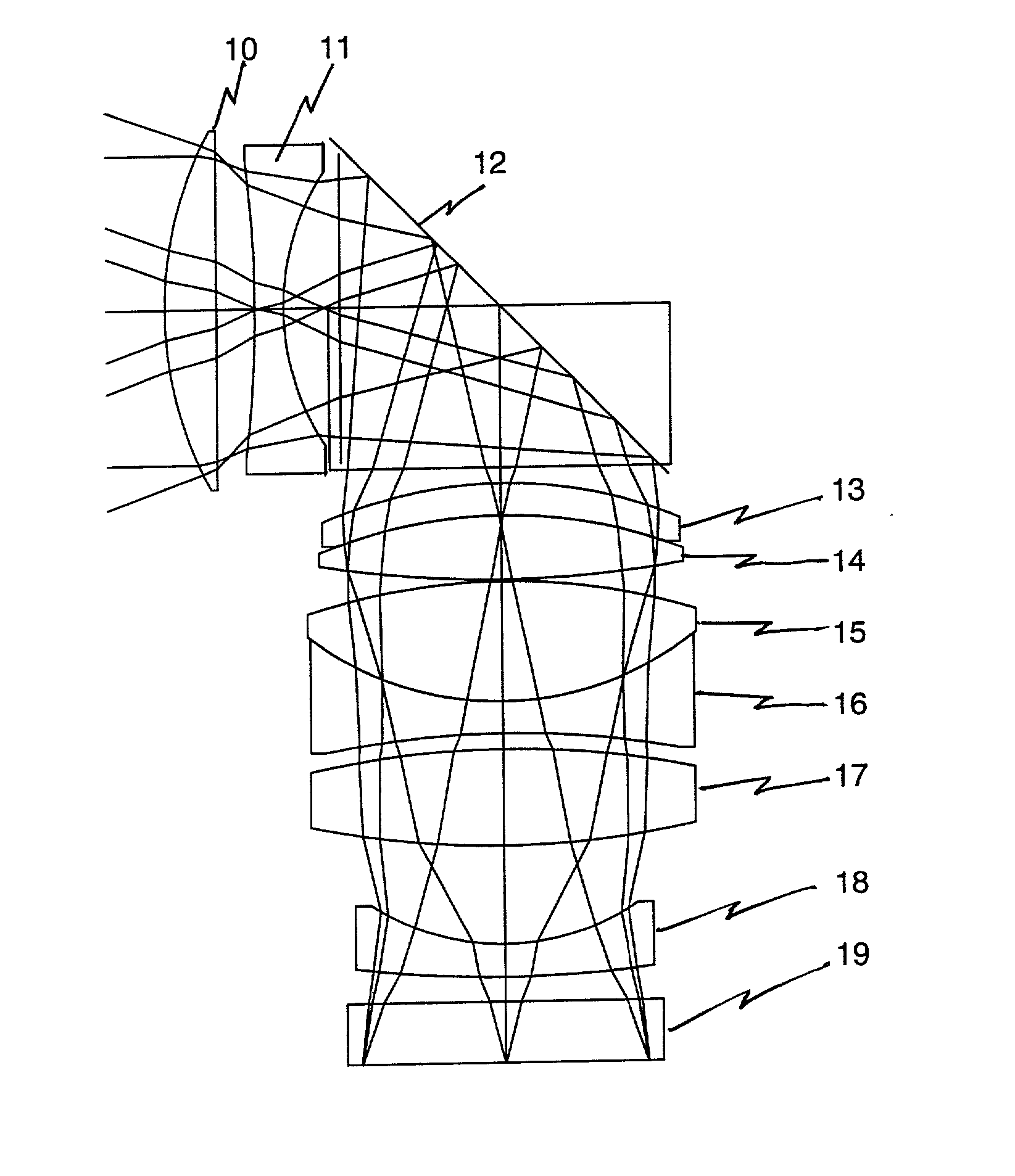
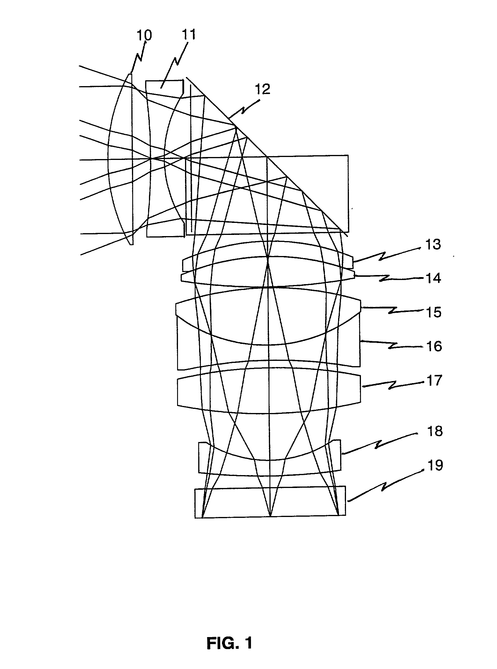
[0015] Referring now to the drawings, and more particularly to FIG. 1, there is shown is a lens ray trace of the objective lens assembly of the invention. Light within the 0.6 to 0.9 micron spectral band from a scene enters the first pair of lenses, elements 10 and 11, which together form a negative powered air-spaced doublet. Light then passes through a right-angle fold prism 12, imparting a 90 degree bend in the optical path. Light then passes through a strong positive powered doublet consisting of elements 13 and 14. Element 13 is specifically designed to allow interchangeable use of a standard filter glass (R-64) or a standard clear glass (Schott PK51A) as desired. Light then continues through the doublet consisting of positive powered lens, element 15 and a negative lens, element 16, and then through a positive lens, element 17. The curvatures of lens elements 16 and 17 are matched, such that this group could become a cemented triplet if desired by the lens manufacturer. Light ...


PUM


Abstract

An objective lens assembly for use in an image intensifier over the 0.6 to 0.9 micron spectral bandwidth resulting in a F# within a range of 1.0 to 1.5 and a field of view within the range of 35 to 45 degrees. The assembly includes an air-spaced doublet, a right angle fold prism for bending the optical axis 90 degrees to a reoriented optical axis, two lens subassemblies, and a field flattening lens.

Description

[0001] 1. Field of the Invention[0002] The present invention generally relates image intensifier optical assemblies and more specifically, to an image intensifier optical objective lens that utilizes right angle bends in its optical path.[0003] 2. Description of Prior Art[0004] Image Intensifier night viewing systems have been used by the military since the Korean and Vietnam Wars in the late 1950's and early 1960's. Since then, steady advances in technology have resulted in the development of high performance, compact devices which can offer quality imaging approaching 20 / 30 vision during night conditions under partial moon and starlight. Common to most image intensification systems are three major subassemblies, the objective lens which focuses light from the scene, the intensifier "tube" which amplifies the incoming image and outputs a correlated phosphor display, and an eyepiece for viewing by a human operator. Since the intensification process depends upon amplification of ligh...

Claims


Application Information

Patent Timeline
IPC IPC(8): G02B23/12
CPCG02B23/12
Inventor HALL, JOHN M.
Owner UNITED STATES OF AMERICA THE AS REPRESENTED BY THE SEC OF THE ARMY
Learn More