Probe for use in an infrared thermometer

a technology for infrared thermometers and probes, which is applied in the direction of optical radiation measurement, instruments, applications, etc., can solve the problems of substantial large heat conducting blocks, inability to accurately measure erros, and thermal coupling arrangement comprising fives parts

Inactive Publication Date: 2003-01-23
ORIENTAL SYST TECH
View PDF0 Cites 15 Cited by
  • Summary
  • Abstract
  • Description
  • Claims
  • Application Information

AI Technical Summary

Problems solved by technology

The drawback of this approch is that a substantially large heat conducting block is required.
Without considering the difference of the thermal time constants between the thermopile sensor and the thermistor, measurement erros will inevitably occur when the thermometer is in a dynamic environment.
Furthermore, the thermal coupling arrangement comprising fives parts will complicate the assembly process.
In other words, before the prior art system becomes stable, the thermometer will introduce measurement errors.
Therefore, how to make a thermistor acurrately track the cold junction temperature of a thermopile chip without time lag is an important issue.

Method used


Image

  • Probe for use in an infrared thermometer
  • Probe for use in an infrared thermometer
  • Probe for use in an infrared thermometer

Examples


first embodiment

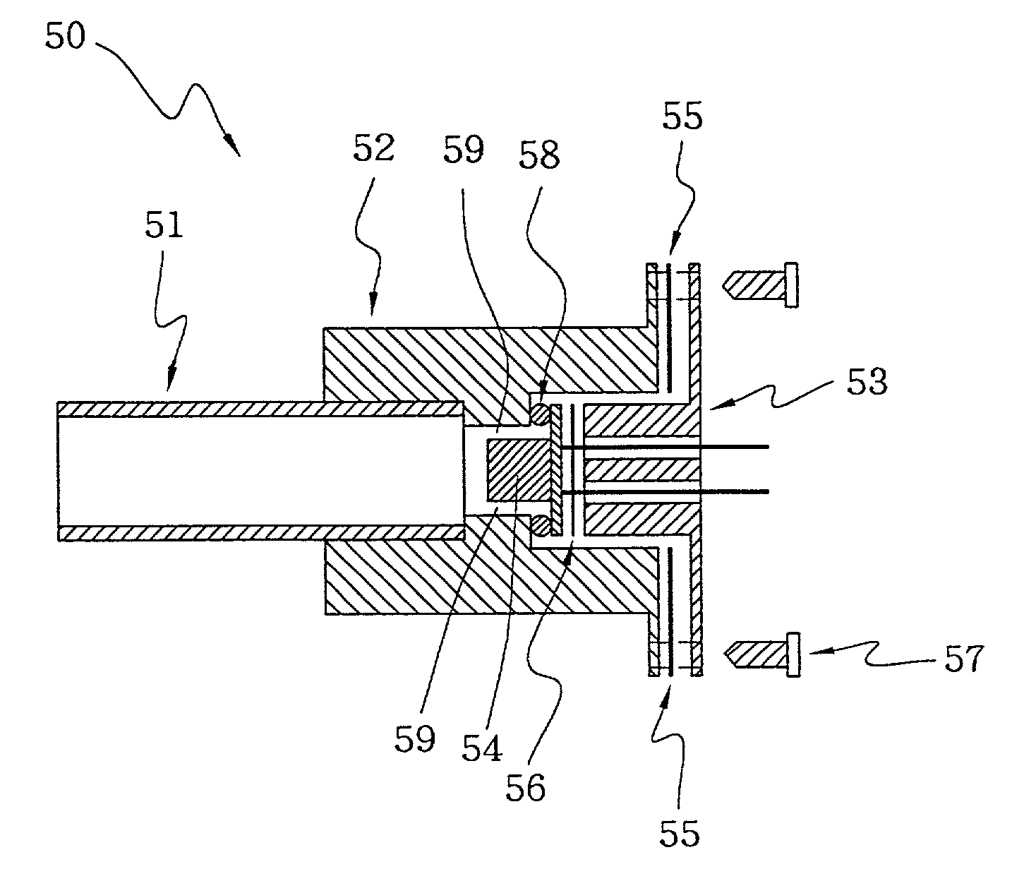
[0037] FIG. 5 shows probe 50 of an infrared thermometer according to the present invention. Probe 50 comprises waveguide 51, first heat sink 52, second heat sink 53, IR sensor 54, O-ring 58, first silicon film 55 and second silicon film 56. Waveguide 51 directs the thermal radiation emitted from the eardrum and nearby tissues to IR sensor 54 and generates corresponding electronic signals. IR sensor 54 outputs electronic signals to a calculating circuit (not shown in the drawings) for showing the human body temperature. First heat sink 52 is thermally coupled to waveguide 51 for reducing the temperature variation of waveguide 51. If the surface of waveguide 51 is coated with a layer of gold with high reflectivity, the thermal mass of first heat sink 52 could be relatively reduced. Second heat sink 53 is thermally coupled to IR sensor 54 for reducing the temperature variation of IR sensor 54. For obtaining a better effect of the heat dissipation, first heat sink 52 and second heat sin...

second embodiment

[0039] FIG. 7 shows probe 70 of an infrared thermometer according to the present invention. The difference from probe 50 of the infrared thermometer shown in FIG. 5 is that probe 70 does not have first silicon film 55 and second silicon film 56. For achieving the purpose of raising the time constant of thermistor 24 to approach that of the cold junction of thermopile chip 23, the present invention changes the internal structure of IR sensor 71 as shown in FIG. 8.

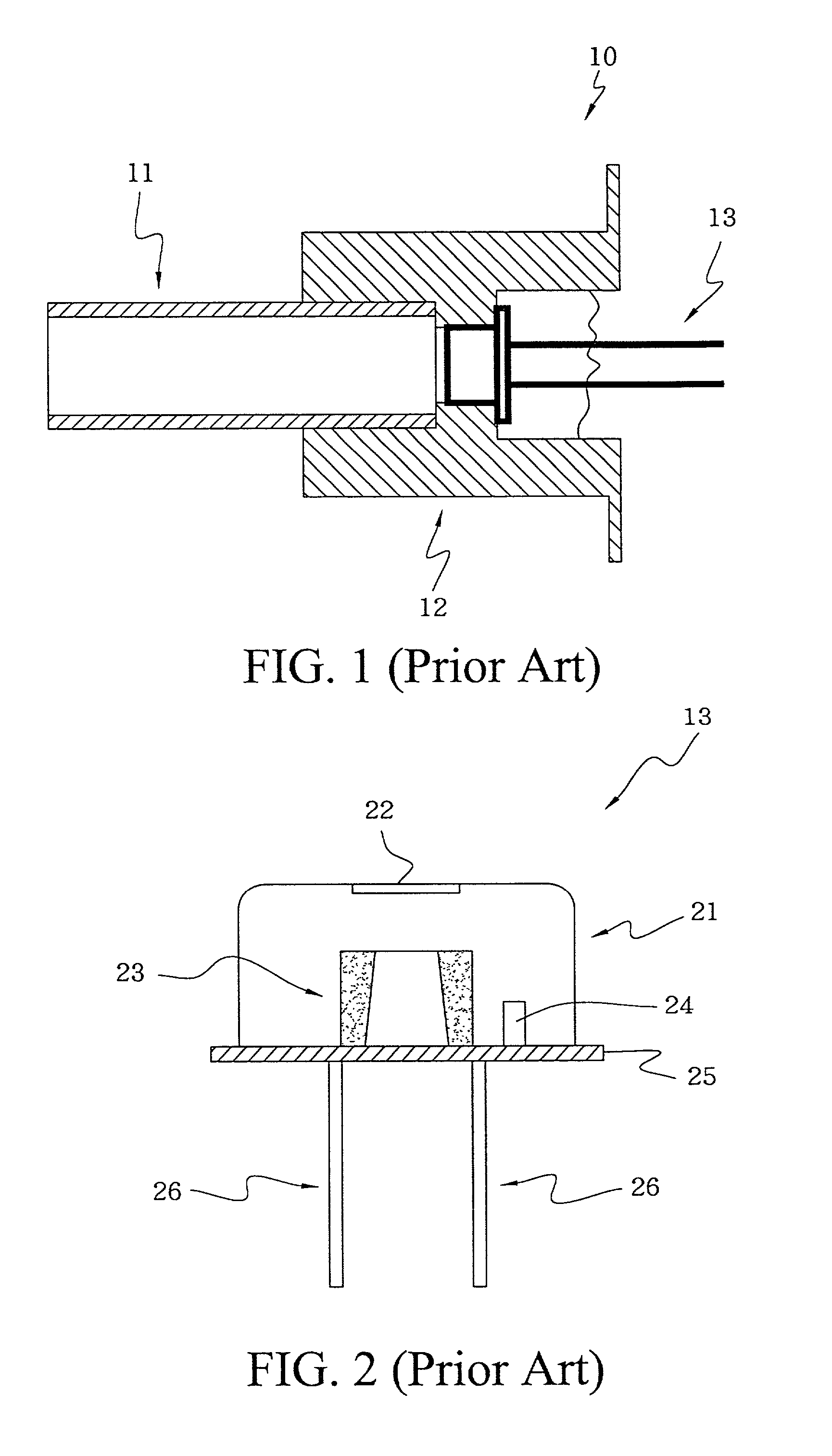
[0040] FIG. 8 shows an IR sensor according to the present invention. The difference from IR sensor 13 shown in FIG. 2 is that substrate 87 with less thermal conductivity (such as a silicon substrate) is positioned between thermistor 84 and base plate 85 of IR sensor 71 to increase the thermal resistance effect of the equivalent model. Like the first embodiment of the present invention, base plate 85 is thermally coupled to second heat sink 53.

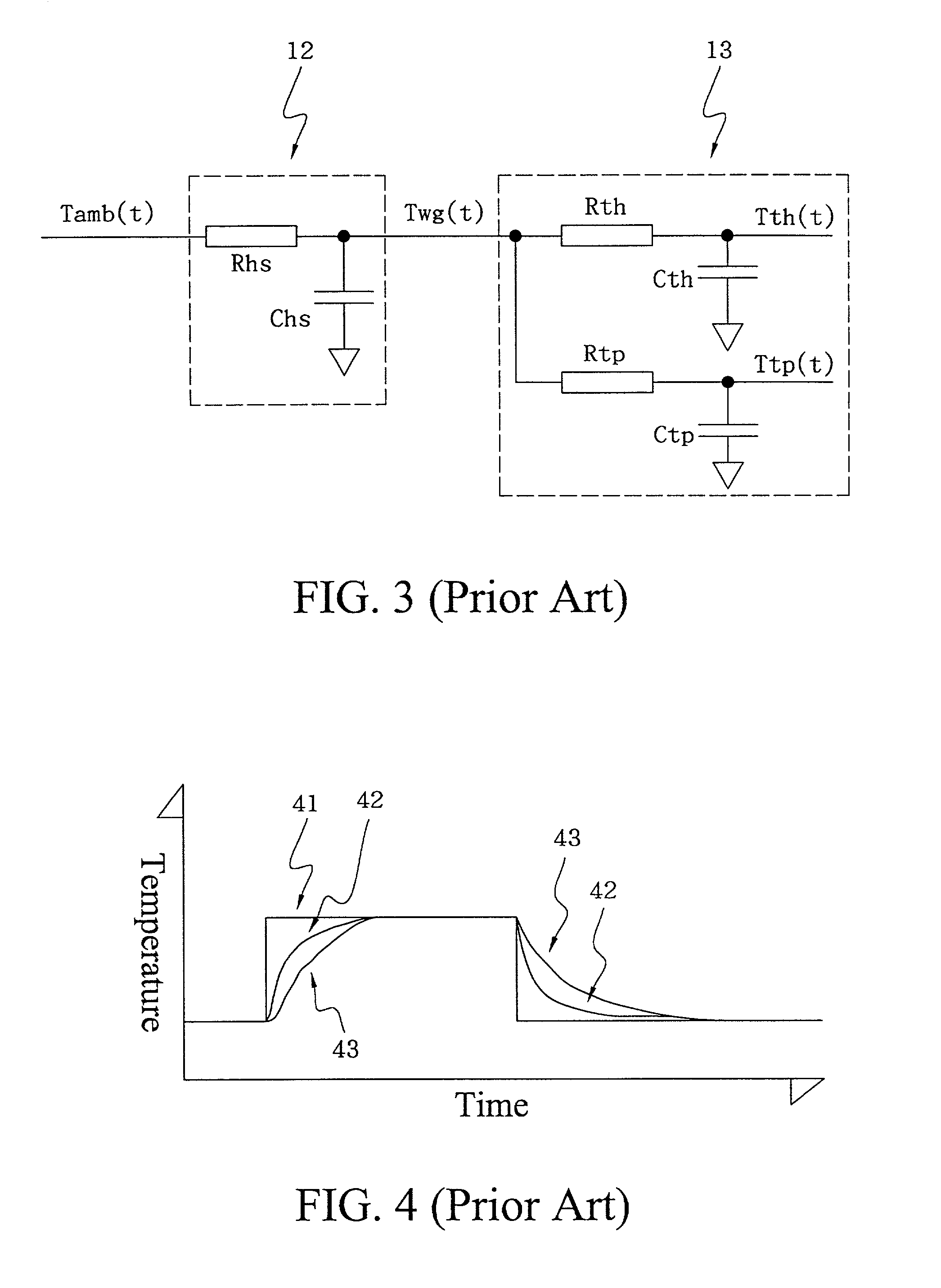
[0041] FIG. 9 shows an equivalent model of probe 70 shown in FIG. 7 responding to t...


PUM


Abstract

The present invention discloses a probe assembly for used in an infrared ear thermometer. Given that the exchanged thermal radiation and the infrared detector's temperature are known, the subject temperature can be calculated according to Stefan-Boltzman's law. To make the Stefan-Boltzman's law applicable in a dynamic environment where temperature may vary greatly, the contact temperature sensor (thermistor) must acuurately and fast track the temperature of the infrared detector (thermopile sensor). By using the heat transfer theorem, the disclosed assembly makes the thermistor accurately track the cold junction temperature of the thermopile chip without being in an isothermal condition. Not only minimizes the measurement error in a dynamic environment, the design of the disclosed probe assembly also makes a samll and compact infrared thermometer possible.

Description

[0001] 1. Field of the Invention[0002] The present invention relates to a probe assembly for use in an infrared ear thermometer, and particularly to a probe assembly which fast adapts to a dynamic enviroment where temperature may vary greatly.[0003] 2. Description of Related Art[0004] Infrared ear thermometers have been extensively used to measure human body temperatures. When using the infrared ear thermometer, the probe is positioned into the ear canal; the thermal radiation emitted by the eardrum and nearby tissues is directed to an infrared sensor through a waveguide; a contact temperature sensor tracks the temperature of the infrared sensor; an electronic circuit processes the signals of the infrared detector and the contact temperature sensor according to Stefan Boltzman's law; and then a calculated human body temperature is displayed on a liquid crystal display.[0005] Nowadays, most infrared ear thermometers employ an infrared detector, which has a thermopile chip and a therm...

Claims


Application Information

Patent Timeline
Patent Type & Authority Applications(United States)
IPC IPC(8): A61B5/01G01J5/00G01J5/16
CPCG01J5/16
Inventor LEE, BURTLEE, ALICHWU, CRUISECHANG, RYAN
Owner ORIENTAL SYST TECH
Why Eureka
Try Eureka