
Pedestrian navigation method and apparatus operative in a dead reckoning mode

Inactive Publication Date: 2003-01-23
ECOLE POLYTECHNIQUE FEDERALE DE LAUSANNE (EPFL)
View PDF0 Cites 280 Cited by
  • Summary
  • Abstract
  • Description
  • Claims
  • Application Information

AI Technical Summary

Benefits of technology

0012] It is an object of the present invention to provide a means of pedestrian navigation by dead reckoning (DR), which does not

Problems solved by technology

However, a simple pedometer cannot indicate the pedestrian's net displacement in a random walk situation, as the direction of motion is not detected.
Limits are quickly reached, however, and reliable navigation cannot be expected when the pedestrian is on soft or uneven ground (e.g. muddy fields, gravel, rubble, etc.).
Under such conditions, steps can be missed out or over-counted, giving rise to accumulated errors quickly rising to unacceptable levels.
Reliance on vertical acceleration can also lead to false step detection when the pedestrian is jumping on the spot.
Moreover, vertical acceleration data alone does not provide a distinction between normal forward motion steps and backward steps.
In other words, it cannot resolve forward / backward motion ambiguity in the pedestrian's step directions.
Similarly, vertical acceleration data alone cannot serve to detect side stepping motion, let alone distinguish between left and right side steps.
This can be an important drawback for pedestrians such as infantrymen, firefighters, sportsmen, people walking through crowds, cluttered environments, etc. who may be expected to make backward and side movements.
Moreover, vertical acceleration data does not provide a means for identifying steps when climbing up or down stairs in the state of the art.
Finally, useful vertical acceleration data is clearly absent when the pedestrian is effecting a crawling movement.

Method used


Image

  • Pedestrian navigation method and apparatus operative in a dead reckoning mode
  • Pedestrian navigation method and apparatus operative in a dead reckoning mode
  • Pedestrian navigation method and apparatus operative in a dead reckoning mode

Examples


Embodiment Construction

of the Algorithm for Extracting Navigation Information from the Sensed Signals and Empirical Data

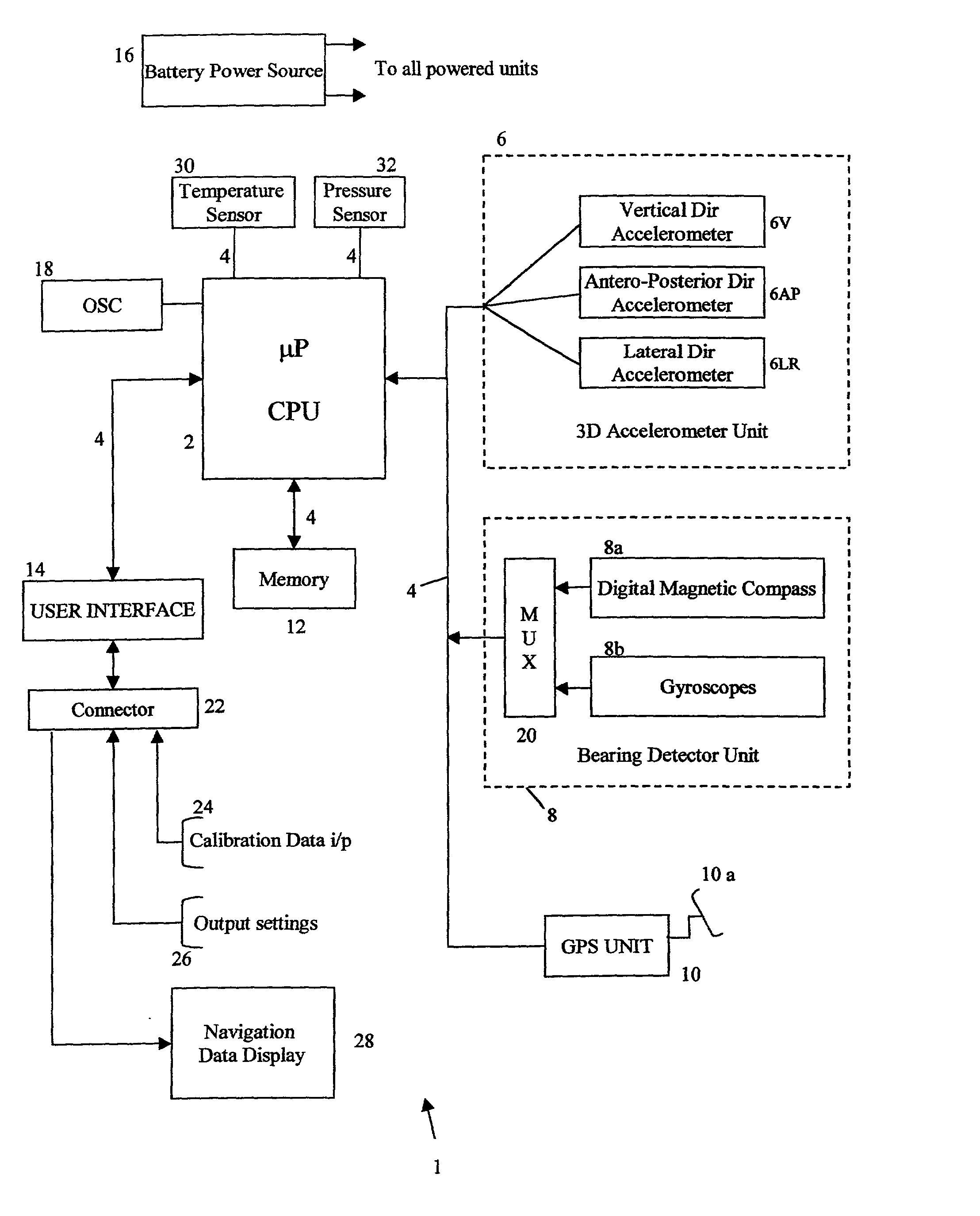
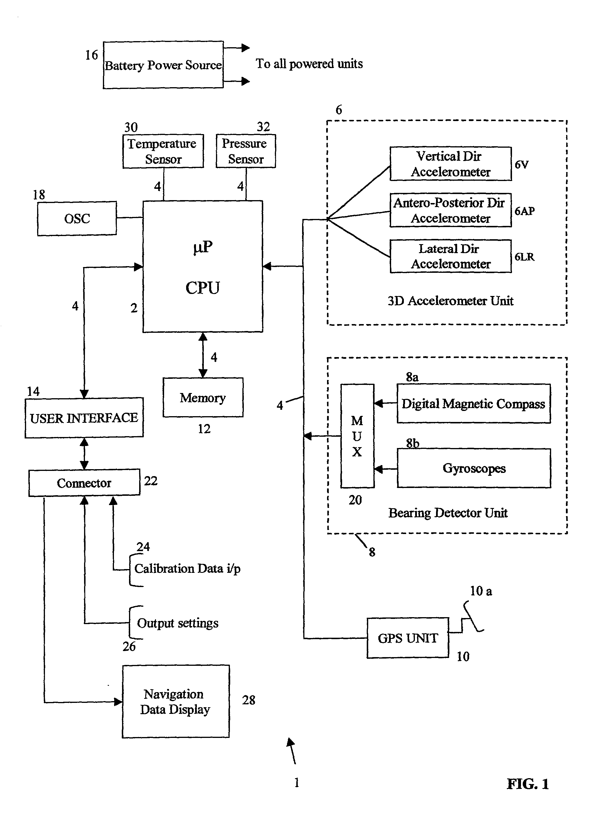
[0301] FIG. 11 outlines the structure of the algorithm used for obtaining position, velocity and orientation from the outputs of the accelerometer unit 6 and bearing detector unit 8, using inputted physiological characteristics and the step model described in the previous section.

[0302] The raw data signals accessed from the accelerator unit 6 and bearing detector unit 8 (box 50) are subjected to preprocessing 52. This involves noise filtering, gain correction, digitization etc. Such functions can be performed by means of circuit elements within the units 6 and 8 and digital signal processing by the microprocessor 2, or by peripheral processors associated with these units.

[0303] The thus pre-processed data is fed into the step model(s) 54 stored in digital form within the memory 12. The physiological characteristics 56 are also fed into the step model(s) 54. They are supplied externally ...


PUM


Abstract

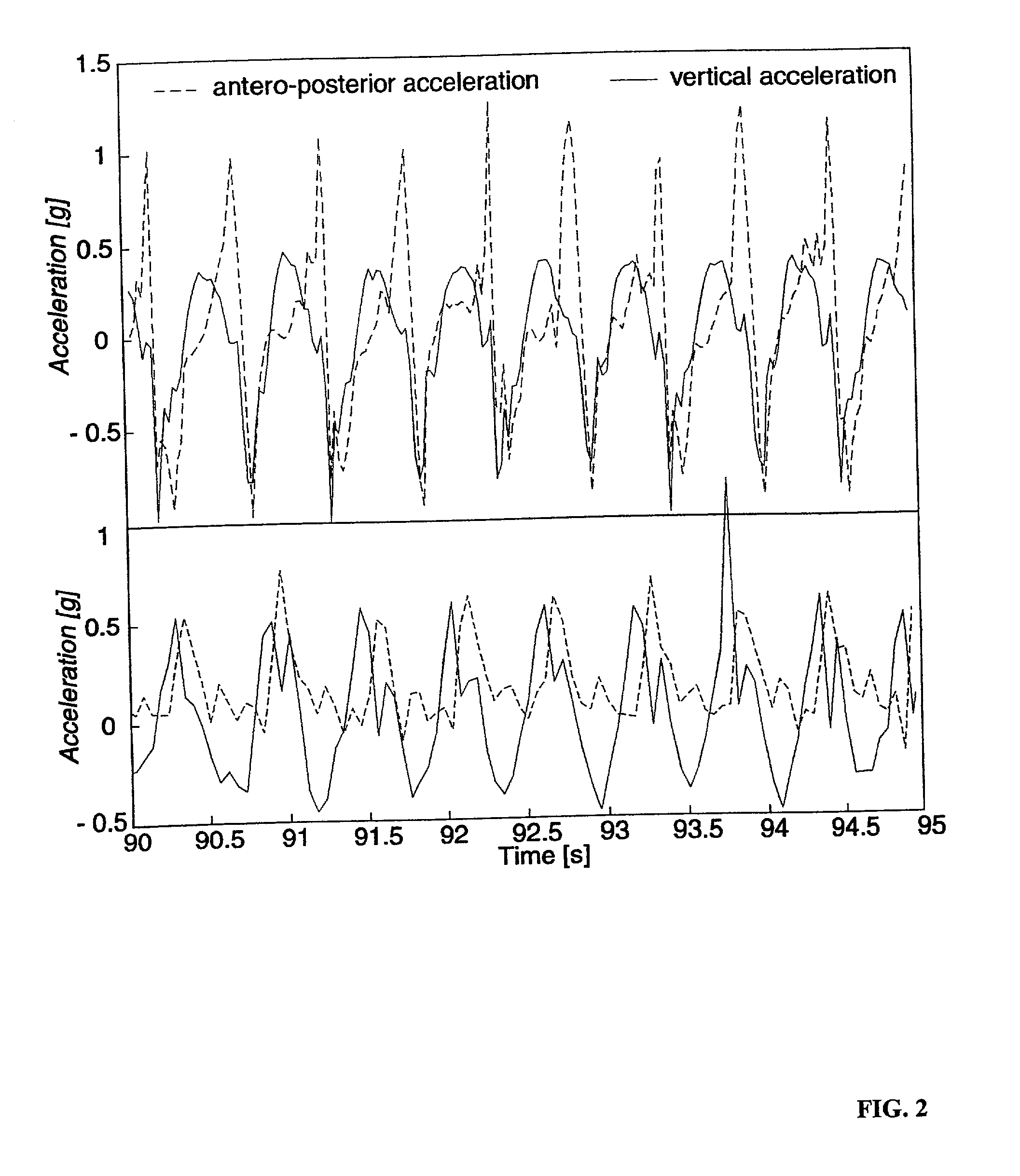
A displacement of a pedestrian is determined from his or her accelerations by detecting accelerations which is substantially non vertical, determining a characteristic feature in the detected accelerations correlated with a step frequency, determining the displacement on the basis of said determined characteristic. The acceleration data can be submitted to waveform analysis to determine an actualized time interval of an occurring feature, such a maximum values, from which it is determined whether the actualized time period falls within determined limit values. The currently detected characteristic feature is then determined as corresponding to a displacement step if the actualized time period falls within said determined limit value. By using non-vertical acceleration measurements, the invention can make it possible to distinguish between forward, backward, left and right stepping movements and take these into account for the navigation.

Description

[0001] 1. Field of the Invention[0002] The present invention relates to the field of pedestrian navigation, based at least partially on a so-called "dead reckoning" (DR) approach, in which the evolving position of a pedestrian is determined from within his or her frame of reference. In other words, navigation by DR does not rely on means which use external positional references, such as GPS (global positioning by satellite), rangefinders, etc. It can however make use of the Earth's magnetic field to determine a compass bearing. Navigation by dead reckoning is required when external position references are not available or exploitable. For instance, GPS data cannot reach a pedestrian in surroundings at least partially hidden from elevational lines of sight: buildings, shadowed zones, dense forests, etc. or in case of jamming. GPS data can be used to complement dead reckoning data and also to establish initial calibration and parameterization.[0003] 2. Prior Art[0004] Pedestrian navig...

Claims


Application Information

Patent Timeline
IPC IPC(8): G01C21/16G01C22/00
CPCG01C21/16G01C21/206G01C22/006G06K9/00348G06F2218/00G01C21/166G06V40/25
Inventor LADETTO, QUENTINGABAGLIO, VINCENTVAN SEETERS, JOSEPHUS
Owner ECOLE POLYTECHNIQUE FEDERALE DE LAUSANNE (EPFL)
Learn More