Hook commutator

a commutator and hook technology, applied in current collectors, dynamo-electric machines, electrical apparatus, etc., can solve the problems of shortening the service life of electric motors and reducing electrical properties

Inactive Publication Date: 2003-01-30
ROBERT BOSCH GMBH
View PDF1 Cites 8 Cited by
  • Summary
  • Abstract
  • Description
  • Claims
  • Application Information

AI Technical Summary

Problems solved by technology

This reduces the electrical properties, such as the transition resistance between the carbon and the lamination or the travel properties of a brush on a carbon surface, or shortens the service life of an electric-motor armature.

Method used


Image

  • Hook commutator
  • Hook commutator

Examples


Embodiment Construction

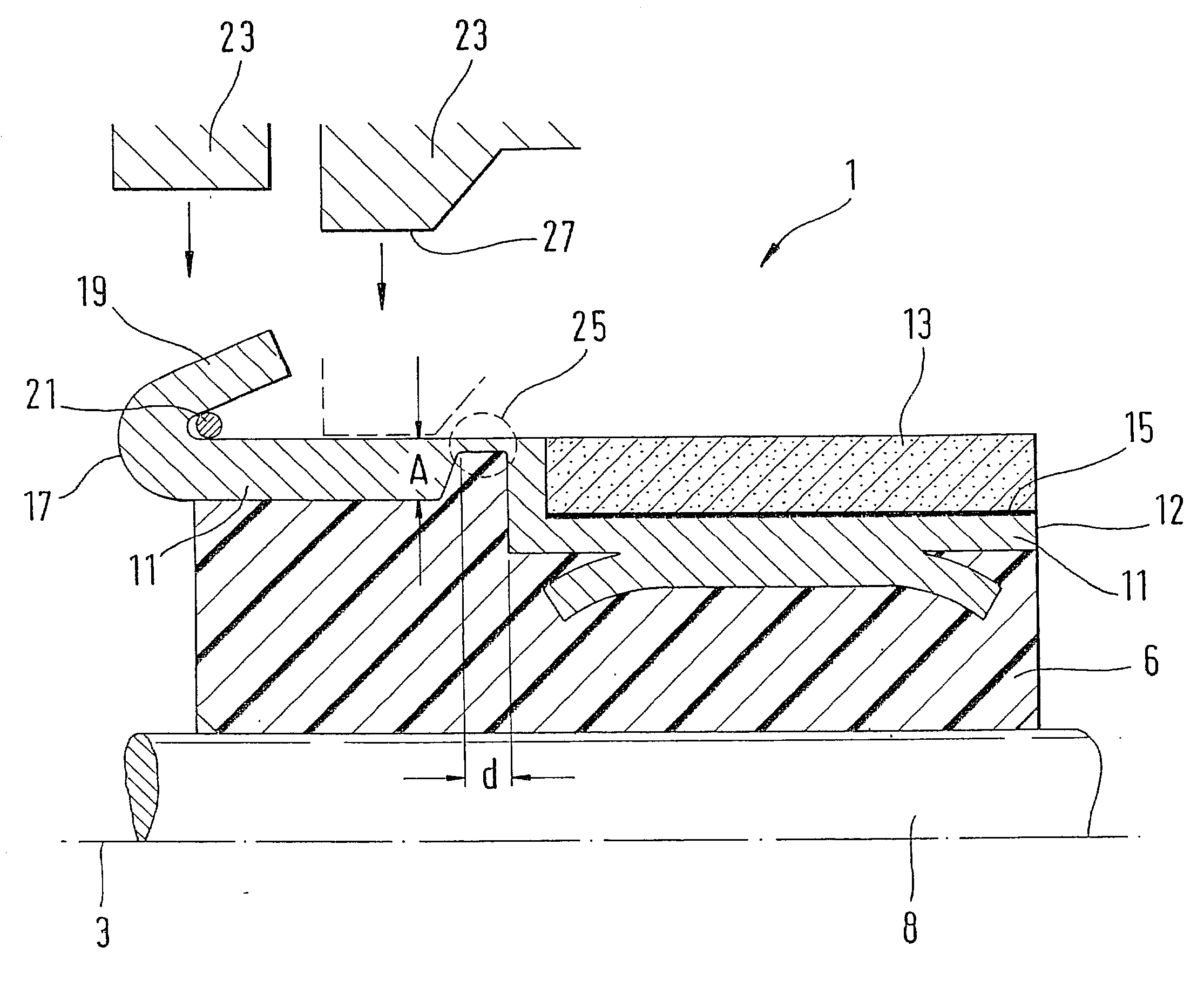
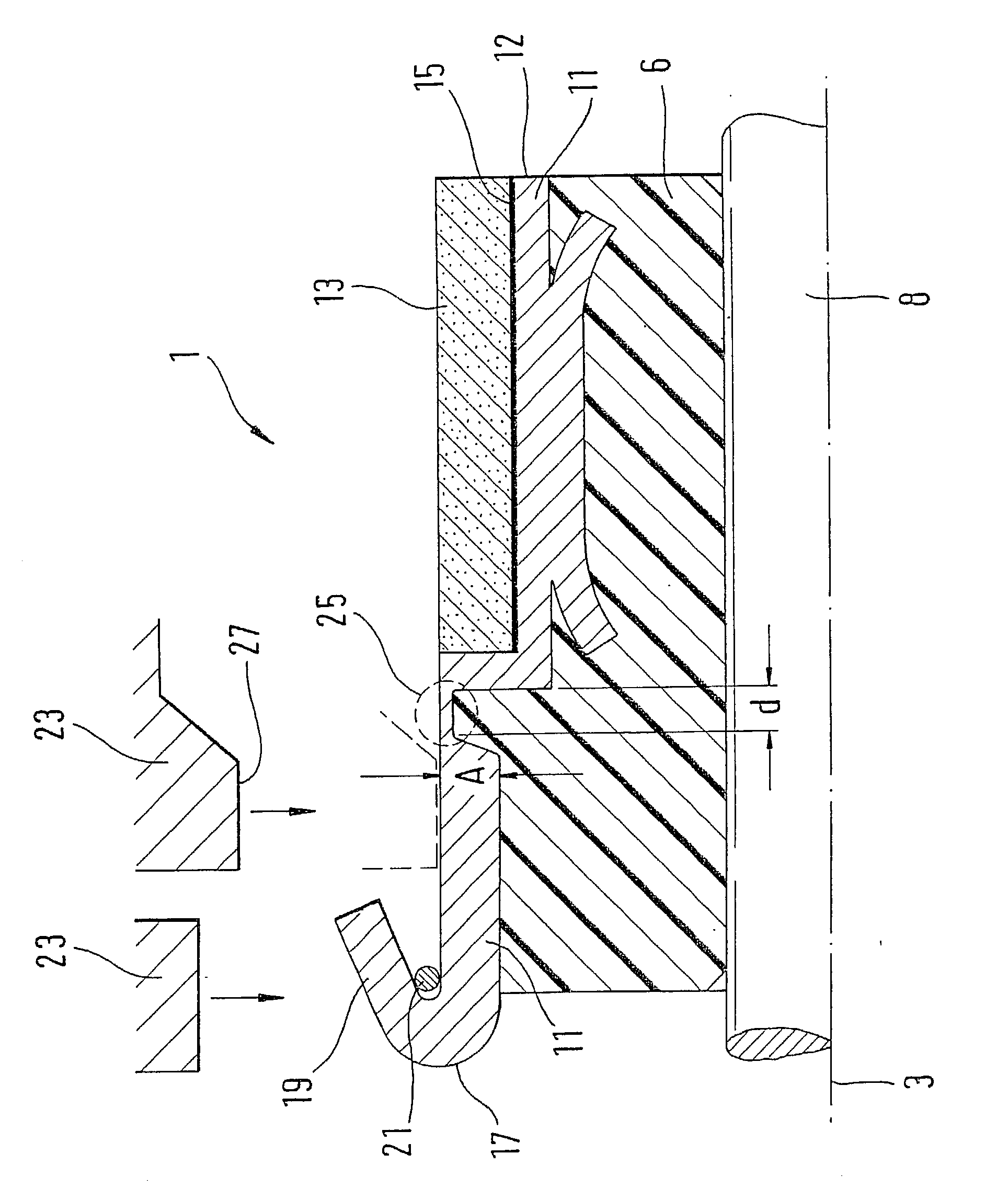
[0011] The drawing shows a hook commutator 1 of an otherwise known electric-motor armature in axial cross section. The hook commutator 1 has an axis of symmetry 3. A support body 6, for instance, is disposed on a rotor shaft 8 of the electric-motor armature. At least one lamination 11 of electrically conductive material is secured to this support body 6. This is accomplished for instance by spray-coating the lamination 11 at least partially with plastic, which for instance forms the material for the support body 6. However, the lamination 11 can also be secured to the support body 6 by other fastening methods.

[0012] On a portion of its one axial end 12, the lamination 11 has a carbon segment 13, which is secured to the lamination 11 by a soldered connection 15. However, the invention is not limited to a carbon segment 13 but instead encompasses any segments that are connected to the lamination 11 and are heat-sensitive. On the other axial end 17 of the lamination 11, a commutator ho...


PUM


Abstract

In a hook commutator of the prior art, a soldered connection (15), which connects a carbon segment (13) to a lamination (11) can become detached, since in the hot staking process for securing the winding wire, heat is produced. A hook commutator (1) of the invention has reduced thermal conduction in a region between the commutator hook (19) and the carbon segment (13), and thus the soldered connection (15) is protected against excessively high heat.

Description

PRIOR ART[0001] The invention is based on a hook commutator for an electric-motor armature as generically defined by the preamble to claim 1.[0002] A hook commutator for an electric-motor armature has laminations, to which the electric current is transmitted by carbon brushes. A winding wire of the rotatably supported electric-motor armature is electrically connected to the lamination. For producing the electric-motor armature with a hook commutator, among other provisions the winding wire is wrapped around one commutator hook each of the lamination of the hook commutator. In a required process of connecting the winding wire and the commutator hook, a constantly good mechanical and electrical quality of the connection of the commutator hook and winding wire is crucial. One connection process employed is known as hot staking. In this process the hook is deformed in such a way that the wire is clamped in place. An electrical voltage is then applied, so that the commutator hook and the...

Claims


Application Information

Patent Timeline
Patent Type & Authority Applications(United States)
IPC IPC(8): H01R39/32H02K13/00
CPCH01R39/32H02K13/00
Inventor LUEDTKE, ULRICH
Owner ROBERT BOSCH GMBH
Why Eureka
Try Eureka