
Semiconducting ceramic material, process for producing the ceramic material, and thermistor

a technology of semiconducting ceramics and ceramic materials, which is applied in the direction of positive temperature coefficient thermistors, applications, manufacturing tools, etc., can solve the problems of difficult to completely re-oxidize semiconducting ceramic materials, process is not necessarily satisfactory, and ceramic material resistance becomes high

Inactive Publication Date: 2003-02-13
MURATA MFG CO LTD
View PDF5 Cites 11 Cited by
  • Summary
  • Abstract
  • Description
  • Claims
  • Application Information

AI Technical Summary

Benefits of technology

[0010] Another object of the present invention is to provide a process for producing a BaTiO.sub.3-type semiconducting ceramic material which exhibits excellent PTC characteristics, which process comprises firing the ceramic material in a reducing atmosphere and re-oxidizing the ceramic material.
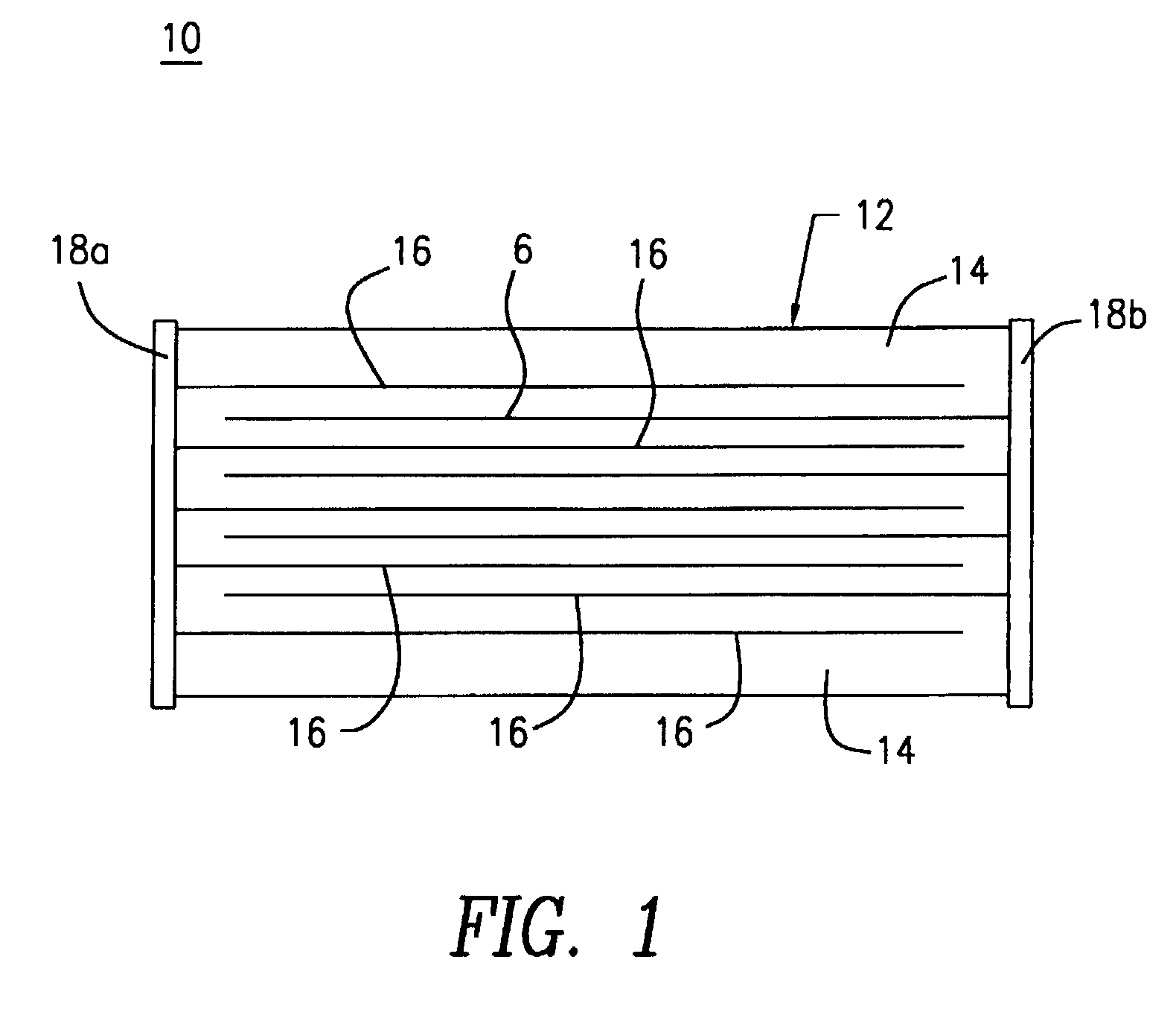
[0011] Another object of the present invention is to provide a thermistor comprising a BaTiO.sub.3-type semiconducting ceramic material which exhibits excellent PTC characteristics, the ceramic material having undergone firing in a reducing atmosphere and re-oxidation.
[0018] When the semiconducting ceramic material is fired at low temperature, the density of the material after sintering can be appropriately reduced and pores through which oxygen passes during re-oxidation can be established. As a result, the semiconducting ceramic material exhibits excellent PTC characteristics.
[0019] Specifically, when the semiconducting ceramic material is fired at a temperature about 25.degree. C. or more lower than the sintering completion temperature, the sintering completion temperature being the temperature at which the density of the material is maximized, the semiconducting ceramic material exhibits excellent PTC characteristics.
[0020] When the relative density of the semiconducting ceramic material after sintering is about 85-90%, the ceramic material exhibits excellent PTC characteristics.
[0022] In the present invention, the semiconducting ceramic can be produced from an inexpensive material used into a solid-state process instead of an expensive wet process.

Problems solved by technology

However, it is difficult to completely re-oxidize the semiconducting ceramic material at a temperature sufficiently low to prevent oxidation of the internal electrode formed of a base metal.
However, such a process is not necessarily satisfactory.
However, when the firing temperature is excessively low, the resistance of the ceramic material becomes high.

Method used


Image

  • Semiconducting ceramic material, process for producing the ceramic material, and thermistor
  • Semiconducting ceramic material, process for producing the ceramic material, and thermistor

Examples


Embodiment Construction

, Example 2, Example 3 and Comparative Example, the firing temperatures of the ceramic material are 1,150.degree. C., 1,200.degree. C., 1,250.degree. C. and 1,300.degree. C., respectively. Table 1 shows firing temperature, re-oxidation temperature, mean grain size, and relative density for each ceramic material. Table 1 also shows the resistance of the monolithic PTC thermistor comprising the ceramic material at room temperature; the logarithm of the maximum resistance of the PTC thermistor (R.sub.max) to the resistance thereof at 25.degree. C. (R.sub.25); i.e., log (R.sub.max / R.sub.25); and the withstand voltage of the PTC thermistor. The re-oxidation temperature of each semiconducting ceramic material was optimized on the basis of the firing temperature thereof. In the Comparative Example, the semiconducting ceramic material was re-oxidized at 800.degree. C., which is the upper limit for preventing oxidation of Ni.

1 TABLE 1 Re- Mean Resistance Firing oxidation grain Relative at ro...


PUM

PropertyMeasurementUnit
Fractionaaaaaaaaaa
Fractionaaaaaaaaaa
Angleaaaaaaaaaa

Abstract

A BaTiO3-type semiconducting ceramic material which has undergone firing in a reducing atmosphere and re-oxidation, wherein the relative density of the ceramic material after sintering is about 85-90%. A process for producing the semiconducting ceramic material of the present invention and a thermistor containing the semiconducting ceramic material are also disclosed.

Description

[0001] This is a divisional of U.S. Patent Application Serial No. 09 / 705,049, filed Nov. 2, 2000.[0002] 1. Field of the Invention[0003] The present invention relates to a semiconducting ceramic material, a process for producing the ceramic material and a thermistor comprising the ceramic material. More particularly, the present invention relates to a BaTiO.sub.3-type semiconducting ceramic material which exhibits the characteristic of positive temperature coefficient of resistance (PTC characteristics), to a process for producing the ceramic material and to a thermistor comprising the ceramic material.[0004] 2. Background Art[0005] Conventionally, a BaTiO.sub.3-type semiconducting ceramic material is widely employed in the manufacture of PTC thermistors since the ceramic material exhibits the characteristic of positive temperature coefficient of resistance (PTC characteristics). The PTC thermistor is widely employed for the demagnetization of a cathode-ray tube or in a heater.[0006]...

Claims


Application Information

Patent Timeline
IPC IPC(8): C04B35/46H01C7/02H01C17/065H01C17/26H05B3/14
CPCH01C7/025H01C17/06533H01C17/265H01C7/02
Inventor NIIMI, HIDEAKIANDO, AKIRAKAWAMOTO, MITSUTOSHIKODAMA, MASAHIRO
Owner MURATA MFG CO LTD
Learn More