Multilayer PTC thermistor

Active Publication Date: 2012-03-08
TDK CORPARATION
View PDF4 Cites 32 Cited by
  • Summary
  • Abstract
  • Description
  • Claims
  • Application Information

AI Technical Summary

Benefits of technology

[0016]The ceramic body in the multilayer PTC thermistor of the invention preferably has the glass component diffused in the pores (open pores) of the ceramic layer, to be adjacent to the glass layer, and the glass layer thickness is preferably greater than the thickness of the diffused portion (diffusion layer). If the ceramic body in the multilayer PTC thermistor of the invention is formed using glass having an alkali oxide content of no greater than 0.8 mass %, it will be possible to accomplish firing at a temperature for a satisfactory flow property of the glass during firing. This will allow permeation of the glass into the open pores of the ceramic body, which is a porous body. It will thus be possible to form a diffusion layer comprising the glass component on the surface layer of the ceramic body. On the other hand, if the diffusion layer is thicker than the glass layer, pinholes may be generated in the glass layer due to variations (deviations) in diffusion depending on the location. In addition, the alkaline component will tend to diffuse into the interior of the ceramic body, altering the PTC characteristics. By forming a diffusion layer on the surface layer of the ceramic body, and limiting the thickness to no greater than the thickness of the glass layer, it is possible to obtain a multilayer PTC thermistor with even more excellent PTC characteristics, while adequately minimizing deterioration of the ceramic body by plating treatment.
[0017]The ceramic body in the multilayer PTC thermistor of the invention preferably has pores containing an oxidizing gas. This will allow a multilayer PTC thermistor to be obtained that has minimized reduction of the ceramic body and can maintain excellent PTC characte

Problems solved by technology

However, it has been found that fine pinholes are generated in the alkaline glass layer that covers the ceramic body surface, and that the plating solution infiltrates into the ceramic body through these pinholes, creating outer appearance defects where the plating adheres at these sections, and leading to variation in characteristics after plating treatment.
On the other hand, while formation of

Method used


Image

  • Multilayer PTC thermistor
  • Multilayer PTC thermistor
  • Multilayer PTC thermistor

Examples


example 1-1

Fabrication of Multilayer PTC Thermistor

Fabrication of Ceramic Body

[0078]As oxide powders there were prepared BaCO3 powder, TiO2 powder, Gd2O3 powder and Nb2O5 powder. The oxide powders were each weighed out in an amount for a final barium titanate-based compound composition according to formula (7). The weighed oxide powders were placed in a nylon pot together with purified water and a pulverizing ball and mixed for 6 hours and dried to obtain a mixed powder.

(Ba0.9985Gd0.0015)0.995(Ti0.9985Nb0.0015)O3  (7)

[0079]After subsequent pre-molding of the mixed powder, it was held for 4 hours in air at 1150° C. and calcined to obtain a calcined body. The calcined body was shredded to form a calcined powder with a mean particle size of 1 μm. The prepared calcined powder was placed in a nylon pot together with a solvent, a binder, a plasticizer, purified water and a pulverizing ball, and mixed therewith for 20 hours using a triple roll to obtain a green sheet slurry. The mixing ratios of the ...

example 1-2

[0100]A multilayer PTC thermistor was obtained in the same manner as Example 1-1, except that the glass powder used was zinc-based glass (main component: ZnO) containing 59.7 mass % ZnO, 27.6 mass % B2O3, 9.4 mass % SiO2 and 3.3 mass % Al2O3, instead of bismuth-based non-alkaline glass, and the firing temperature for formation of the glass layer was changed to 710° C.

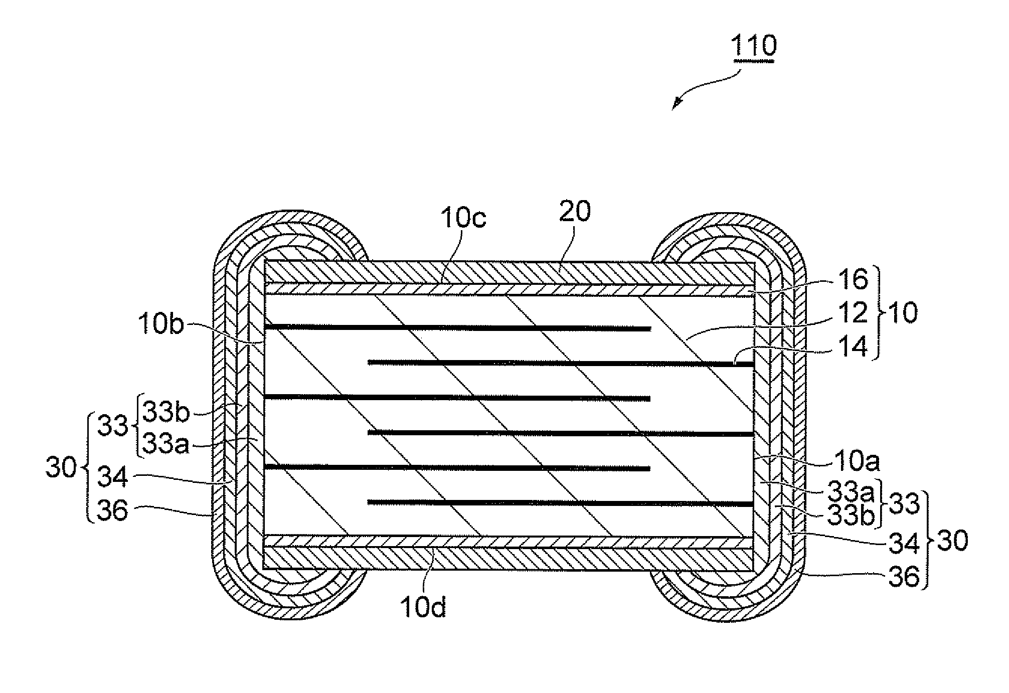
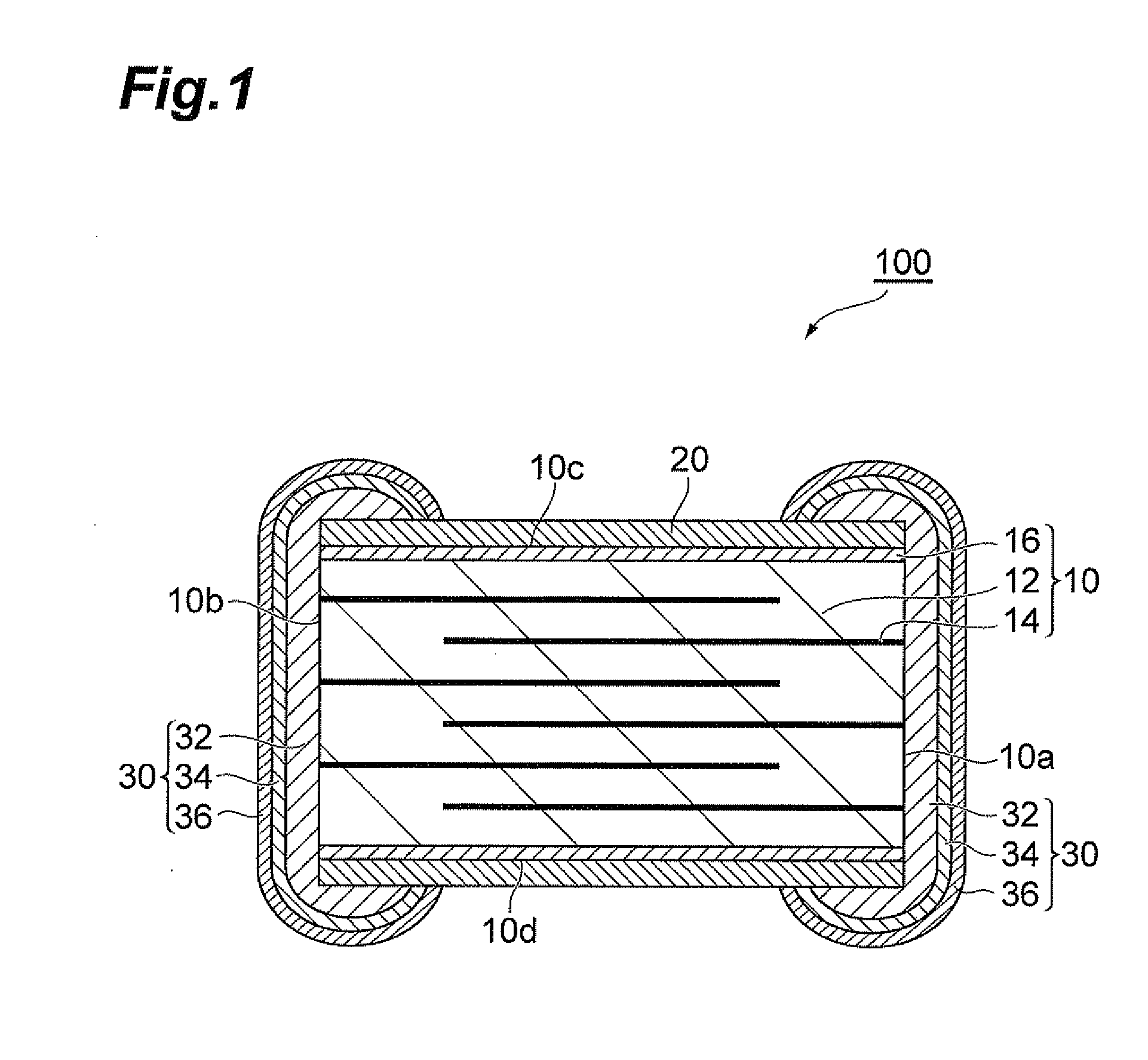
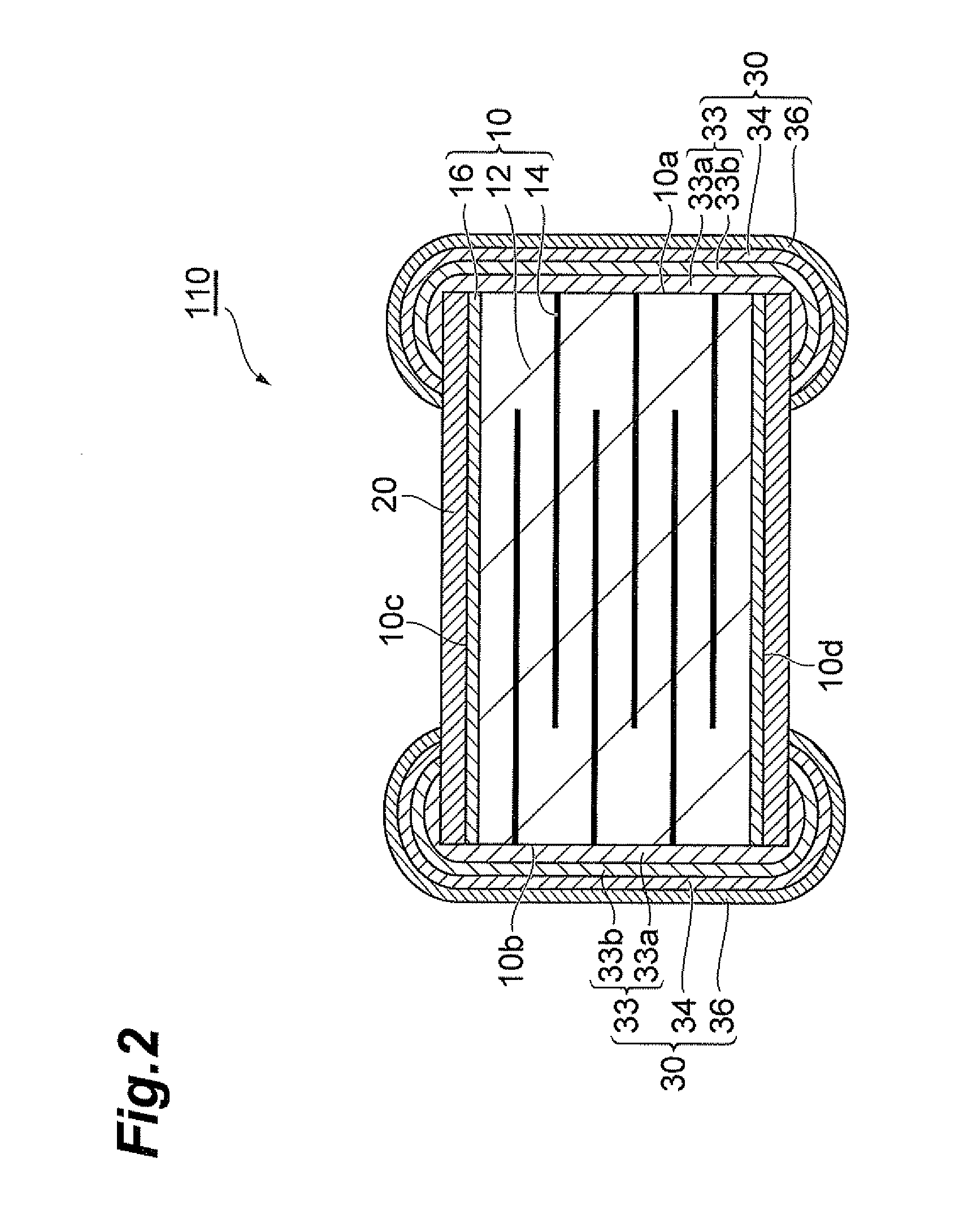
[0101]The multilayer PTC thermistor comprised a ceramic body, a glass layer on its main side, and external electrodes each having a ground electrode layer, a tin plating layer and a nickel plating layer on the end faces, in that order from the ceramic body side. This was used as a multilayer PTC thermistor for Example 1-2. Multilayer PTC thermistors were fabricated by the same procedure, to produce a total of 1000 multilayer PTC thermistors. The softening temperature of the glass component in the glass layer of each multilayer PTC thermistor of Example 2-1 was 631° C., and the crystallization temperature was 750° C. The...

example 1-3

[0104]A multilayer PTC thermistor was obtained in the same manner as Example 1, except that the glass powder used was bismuth-based non-alkaline glass (main component: Bi2O3) containing 84 mass % Bi2O3, 9 mass % ZnO, 4 mass % SiO2 and 3 mass % Al2O3, and the firing temperature for formation of the glass layer was changed to 490° C. The multilayer PTC thermistor comprised a ceramic body, a glass layer on its main side, and external electrodes each having a ground electrode layer, a tin plating layer and a nickel plating layer on the end faces, in that order from the ceramic body side.

[0105]This was used as a multilayer PTC thermistor for Example 1-3. Multilayer PTC thermistors were fabricated by the same procedure, to produce a total of 1000 multilayer PTC thermistors. The softening temperature of the glass component in the glass layer of each multilayer PTC thermistor of Example 1-3 was 410° C., and the crystallization temperature was 470° C. The obtained multilayer PTC thermistor w...


PUM

PropertyMeasurementUnit
Percent by massaaaaaaaaaa
Temperatureaaaaaaaaaa

Abstract

A multilayer PTC thermistor 100 includes a ceramic body 10 having a plurality of ceramic layers 12 and internal electrodes 14 between adjacent ceramic layers 12, external electrodes 30 on the end faces 10a, 10b of the ceramic body 10, and a glass layer 20 on the surfaces 10c, 10d of the ceramic body 10, the glass layer 20 containing an oxide of at least one element selected from the group consisting of zinc and bismuth as the major component, wherein the alkali oxide content of the glass layer is no greater than 0.8 mass %.

Description

BACKGROUND OF THE INVENTION[0001]1. Field of the Invention[0002]The present invention relates to a multilayer PTC thermistor.[0003]2. Related Background Art[0004]PTC (Positive Temperature Coefficient) thermistors are known as thermistors with positive resistance temperature characteristics, or increased resistance with increased temperature. PTC thermistors are constructed by forming at least a pair of opposing electrodes on a material having a positive temperature coefficient. PTC thermistors are utilized in self-regulating heating units, overcurrent protection elements, temperature sensors and the like.[0005]As PTC thermistors there are known polymer PTCs comprising a body formed using materials obtained by mixing resins and metal powders. With polymer PTCs, the temperature coefficient of the resin is greater than that of the metal powder, and therefore the mutual distance between the metal powder increases as the temperature rises, such that the resistance of the body undergoes r...

Claims


Application Information

Patent Timeline
IPC IPC(8): H01C7/13
CPCC01G31/006C01G33/006C04B38/0615H01C7/021C01G35/006C03C3/062C03C3/066C03C8/04C04B35/4682C04B35/62685C04B2235/3201C04B2235/3224C04B2235/3251C04B2235/3255C04B2235/6025C04B2235/616C04B2235/652C04B2235/6582C04B2235/79C04B38/0058
Inventor KAJINO, TAKASHIITOH, KAZUHIKOTANAKA, TEIICHIHITOMI, ATSUSHIOTA, TAKASHI
Owner TDK CORPARATION
Why Eureka
Try Eureka