Fuel cell system

Inactive Publication Date: 2003-02-13
DENSO CORP
View PDF5 Cites 171 Cited by
  • Summary
  • Abstract
  • Description
  • Claims
  • Application Information

AI Technical Summary

Problems solved by technology

However, in this method, during the warm-up operation of the fuel cell, some stack parts generate electric power, and the other stack parts generate no electric power.
Further, fuel gas such as

Method used


Image

  • Fuel cell system
  • Fuel cell system
  • Fuel cell system

Examples


first embodiment

[0055] (First Embodiment)

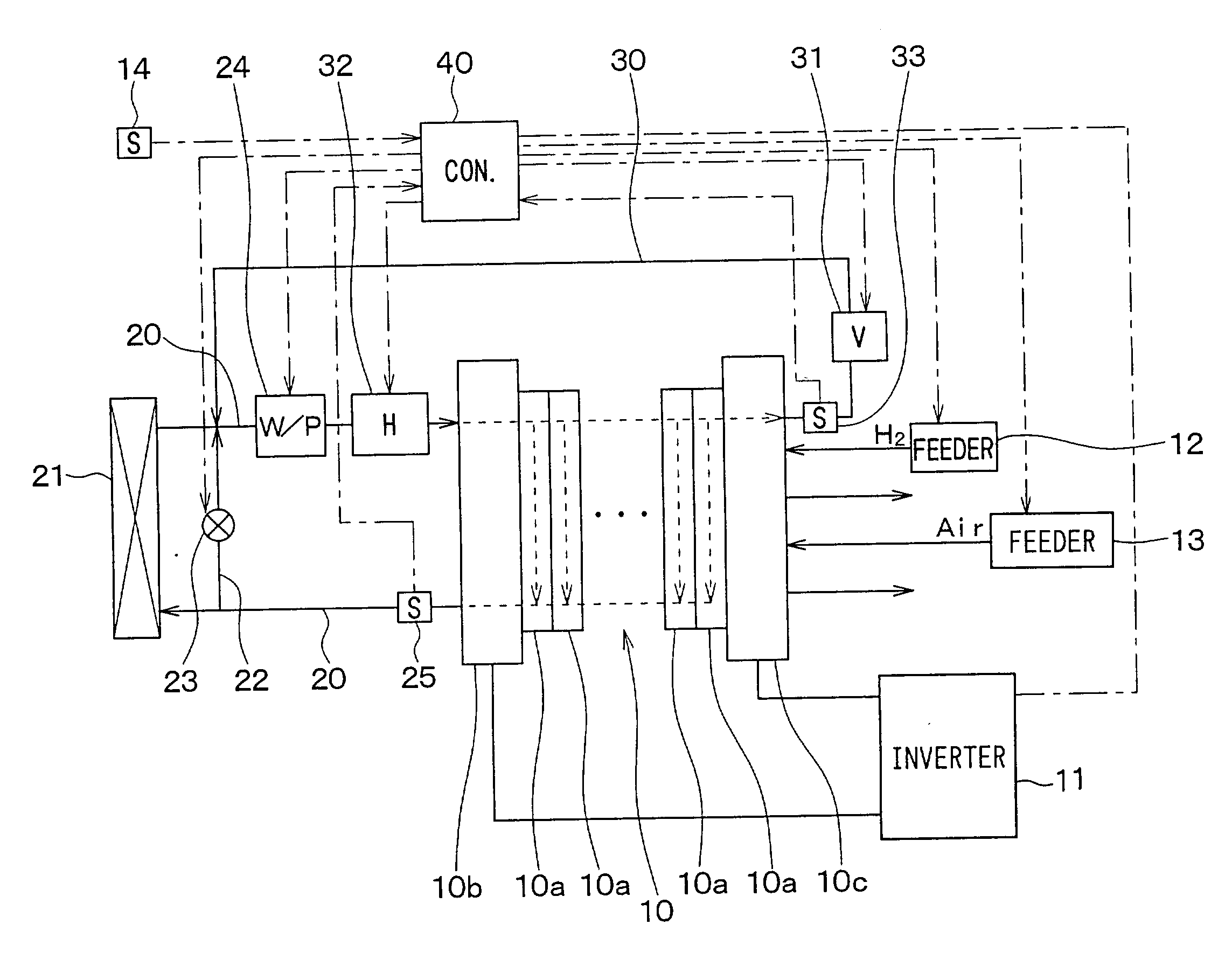
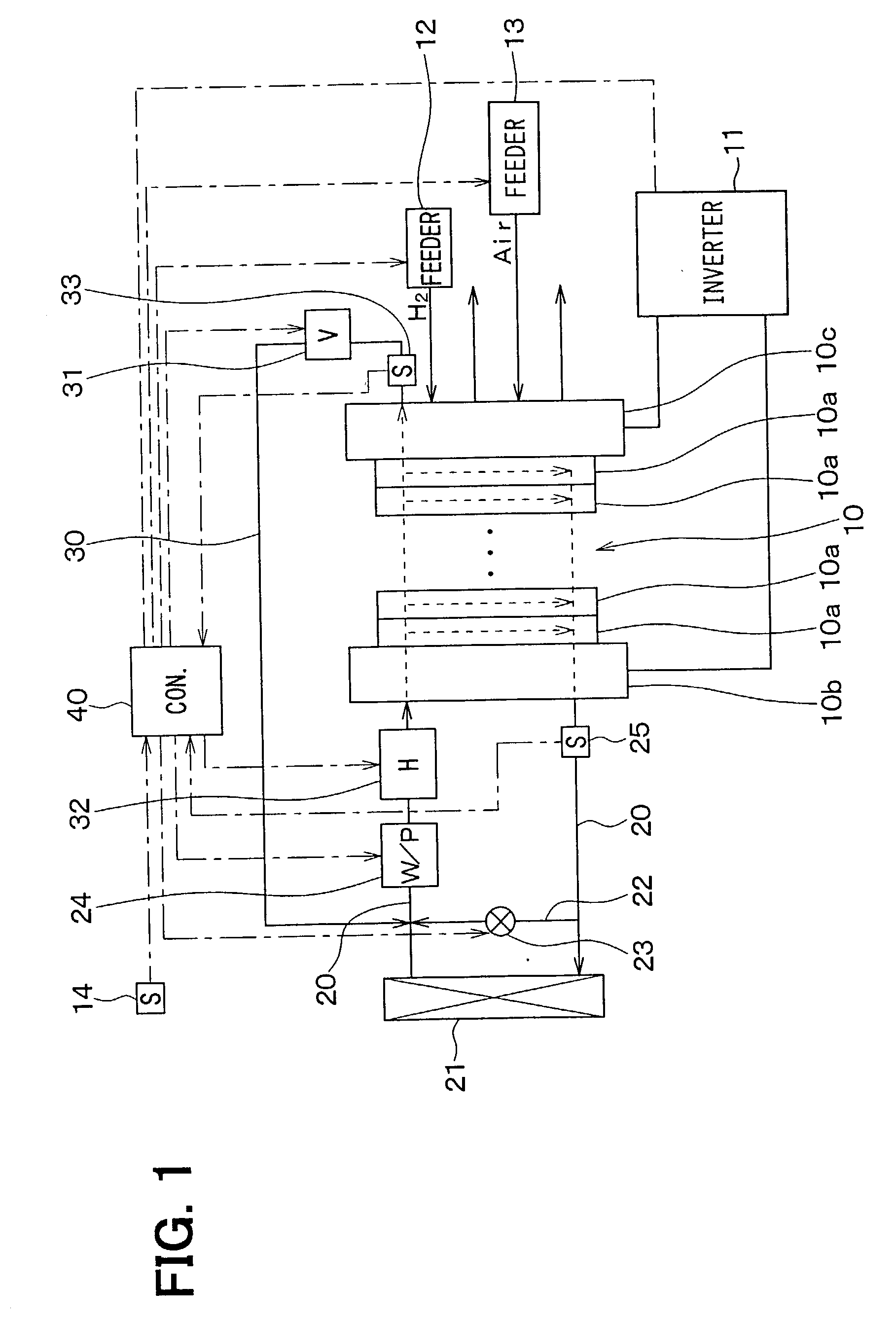
[0056] In the first embodiment, a fuel cell system of the present invention is typically used for an electric vehicle (fuel-cell vehicle) driven by a fuel cell as a power source. As shown in FIG. 1, the fuel cell system according to the first embodiment includes a fuel cell 10, a hydrogen feeder 12, an air feeder 13, a heating-cooling system 20-33, a controller 40 and the like. The fuel cell (FC stack) 10 generates electric power using an electrochemical reaction between hydrogen and oxygen. Here, the hydrogen and the oxygen are used as a fuel gas in the fuel cell 10. In the first embodiment, a solid-polymer electrolyte fuel cell is used as the fuel cell 10, and the fuel cell 10 is constructed by plural cells 10a each of which is used as a unit cell. Each cell 10a is constructed by an electrolyte film sandwiched between a pair of electrodes. Hydrogen and air (oxygen) are supplied to the fuel cell 10. In the fuel cell 10, the following electrochemical reactio...

second embodiment

[0079] (Second Embodiment)

[0080] In the second embodiment, a thermal-medium switching device for switching a flow direction of the thermal medium (cooling water) is added to the fuel cell system in the first embodiment. The thermal-medium switching device switches a flow direction of cooling water circulated into the fuel cell 10 during the partial warm-up operation. In the second embodiment, the same portions as the above-described first embodiment are indicated by the same reference numerals, respectively, and description thereof is omitted.

[0081] As shown in FIG. 4, in the second embodiment, a sub-bypass path 34 is provided to connect the cooling-water circulation path 20 (thermal-medium circulation path) and the bypass path 30. Further, flow switching valves 35, 36 are provided at a connection point between the cooling-water circulation path 20 and the sub-bypass path 34, and at a connection point between the bypass path 30 and the sub-bypass path 34. Two flow passages crossing ...

third embodiment

[0086] (Third Embodiment)

[0087] In the above-described second embodiment of the present invention, the thermal-medium switching device for switching the flow direction of the thermal medium (cooling water) is constructed by the flow-path switching valves 35, 36 and the sub-bypass path 34. However, in the third embodiment, a thermal-medium circulation device capable of switching a flow direction of the thermal medium is used as the thermal-medium switching device. Further, in the third embodiment, the same portions as the above-described embodiments are indicated by the same reference numerals, and description thereof is omitted.

[0088] As shown in FIG. 6, a water pump 24a capable of switching a flow direction of cooling water is provided. The water pump 24a is constructed so that the water inlet side and the water outlet side of the fuel cell 10 can be alternately switched.

[0089] When the fuel-cell partial temperature Tfc becomes equal to or higher than a predetermined temperature, o...


PUM


Abstract

A fuel cell system includes a fuel cell constructed by plural stacked cells, a circulation path through which a thermal medium is circulated into each cell, a heater for heating the thermal medium, a bypass path through which the thermal medium is circulated into a part of each cell while bypassing the other part thereof, and a flow control valve for controlling a flow amount of the thermal medium circulated in the bypass path. The thermal medium can be circulated into only the part of each cell in a warm-up operation, so that the part of each cell is collectively heated. An amount of the thermal medium circulated into the other part of each cell is controlled, so that all of each cell is finally warmed up in the warm-up operation.

Description

[0001] This application is related to and claims priority from Japanese Patent Applications No. 2001-244213 filed on Aug. 10, 2001, No. 2001-383667 filed on Dec. 17, 2001, No. 2002-21635 filed on Jan. 30, 2002, and No. 2002-184948 filed on Jun. 25, 2002, the contents of which are hereby incorporated by reference.[0002] 1. Field of the Invention[0003] The present invention relates to a fuel cell system having a fuel cell that generates electric power by an electrochemical reaction between oxygen and hydrogen. The fuel cell system is suitably used for a movement body such as a vehicle, a ship and a portable generator.[0004] 2. Description of Related Art[0005] In a fuel cell for generating electric power using a chemical reaction between hydrogen and air (oxygen), moisture (water) is generated in the fuel cell due to power generation. In a low temperature environment such as in winter, the water contained in the fuel cell is frozen. Therefore, operation of the fuel cell is not started,...

Claims


Application Information

Patent Timeline
IPC IPC(8): H01M8/02H01M8/04H01M8/24
CPCH01M8/04007H01M8/04029H01M8/04037H01M8/04074H01M8/04097H01M8/04223H01M8/04268H01M8/04358H01M8/04365H01M8/04417H01M8/04723H01M8/04731H01M8/04768H01M8/04955H01M8/241Y02E60/50H01M8/2483H01M8/04302H01M8/04225H01M8/0267H01M8/2457
Inventor SAITO, TOMOHIROKAWAI, TOSHIYUKIOKAMOTO, KUNIOOSAKI, AKIMASAKUDOU, HIROYASU
Owner DENSO CORP
Why Eureka
Try Eureka