

Accelerator pedal module
- Summary
- Abstract
- Description
- Claims
- Application Information
AI Technical Summary
Benefits of technology
Problems solved by technology
Method used
Image

Examples
Embodiment Construction
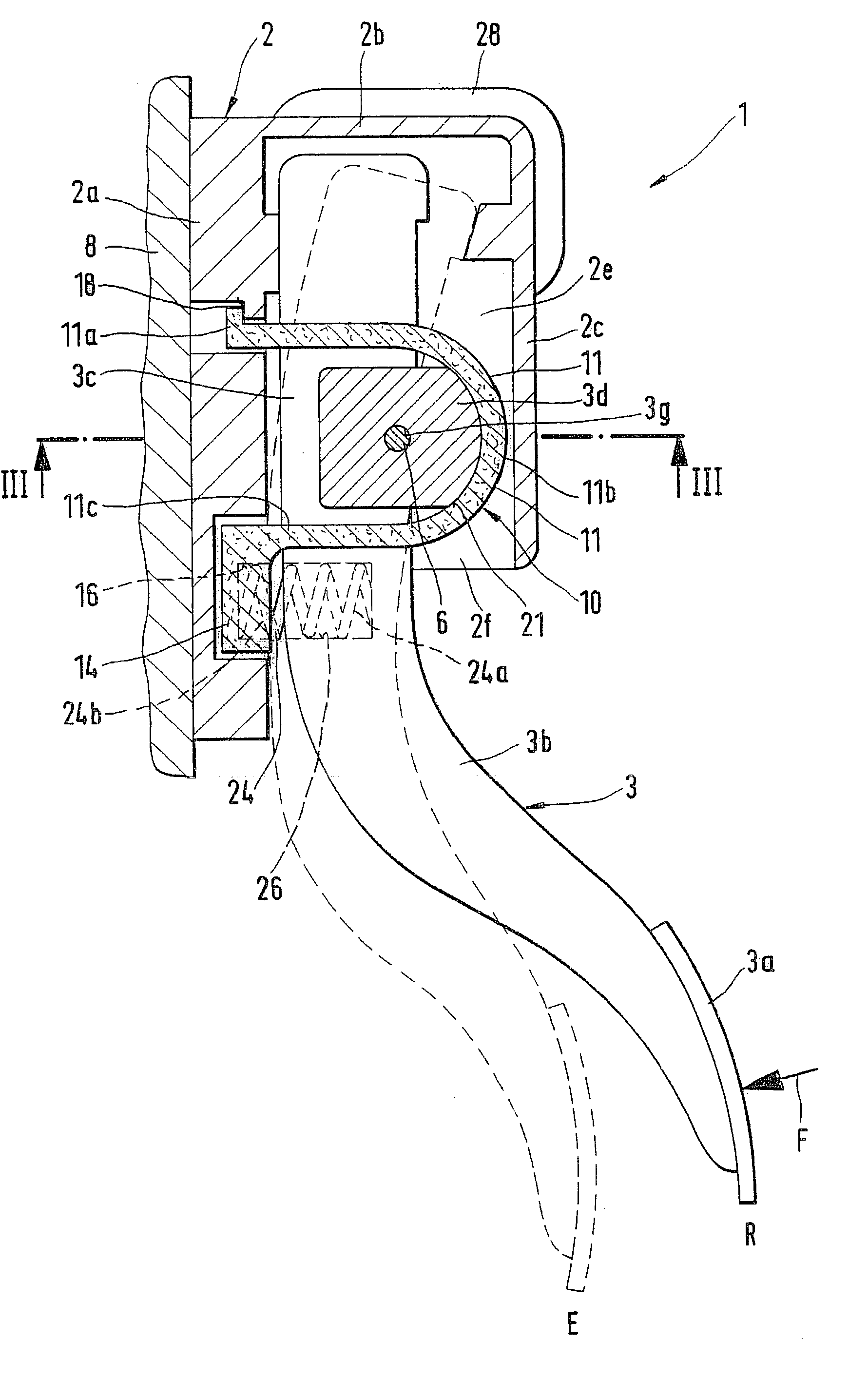
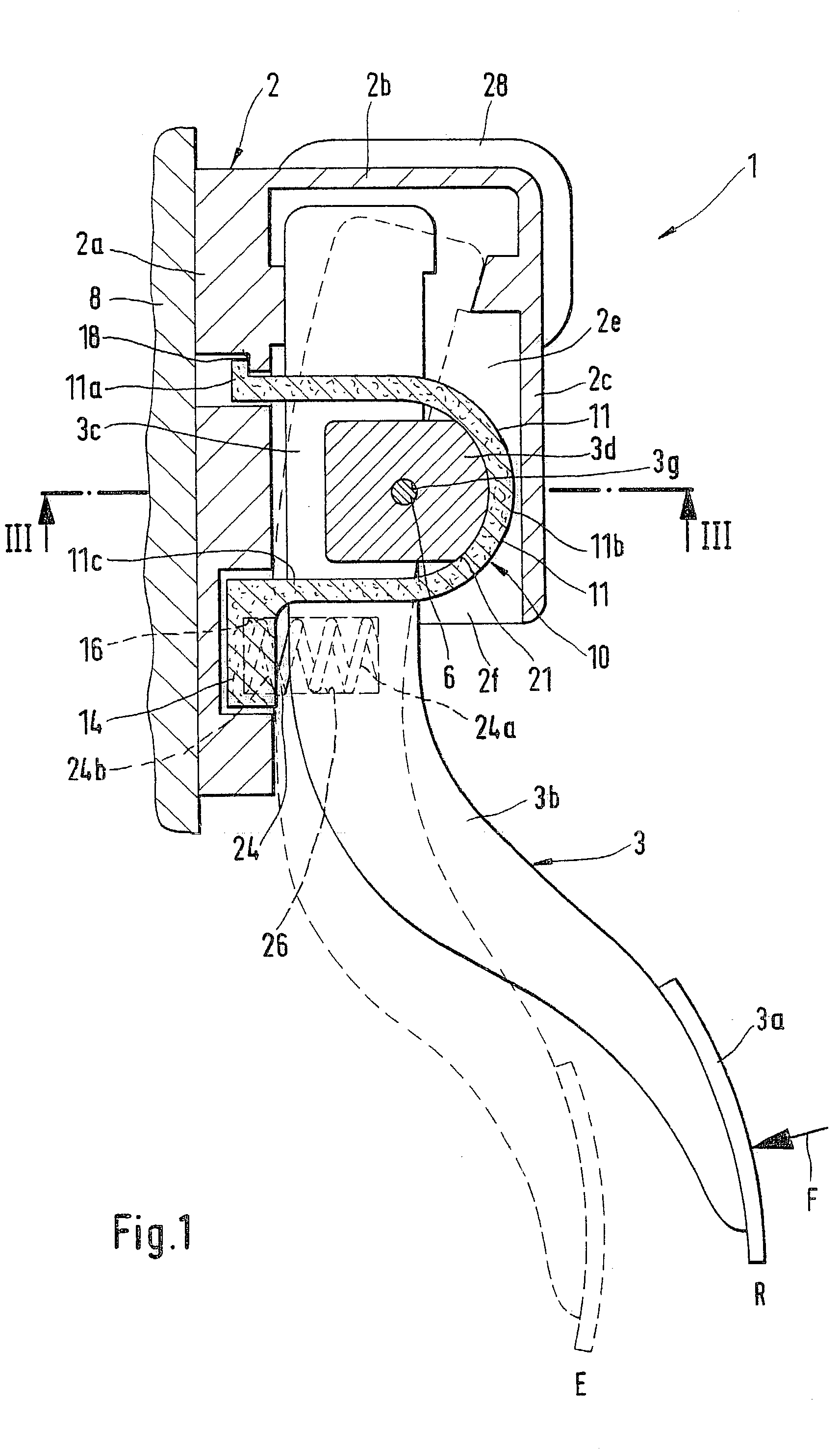
[0025] The accelerator pedal module 1 embodied according to the invention can be used to control different driving engines. For example, the drive engine is an Otto engine whose throttle valve is adjusted with a servomotor. In this instance, the accelerator pedal module is used to transmit electrical signals which are supplied to the servomotor that adjusts the throttle valve. However, the driving engine can also be a diesel engine or an electric motor, for example; in these cases as well, electrical signals are emitted by the accelerator pedal module 1 which, appropriately transformed, control the output but of the driving engine.
[0026] The accelerator pedal module 1 is preferably fastened to a part of the vehicle directly in the vehicle driver's range of action. The pedal lever 3 of the accelerator pedal module 1 is frequently also referred to as the gas pedal.
[0027] In all the figures, parts which are the same or function in the same manner are provided with the same reference nu...
PUM
 Abstract
Description
Claims
Application Information