Magnetically levitated motor and magnetic bearing apparatus

Inactive Publication Date: 2003-03-27
NIDEC SANKYO CORP
View PDF6 Cites 54 Cited by
  • Summary
  • Abstract
  • Description
  • Claims
  • Application Information

AI Technical Summary

Problems solved by technology

However, such an arrangement would increase the axial length because the magnetic bearing apparatuses are disposed at both sides of the motor section, which result in drawbacks such as a lowered natural frequency and a lowered critical speed.
However, this structure has a drawback in that the nega

Method used


Image

  • Magnetically levitated motor and magnetic bearing apparatus
  • Magnetically levitated motor and magnetic bearing apparatus
  • Magnetically levitated motor and magnetic bearing apparatus

Examples


first embodiment

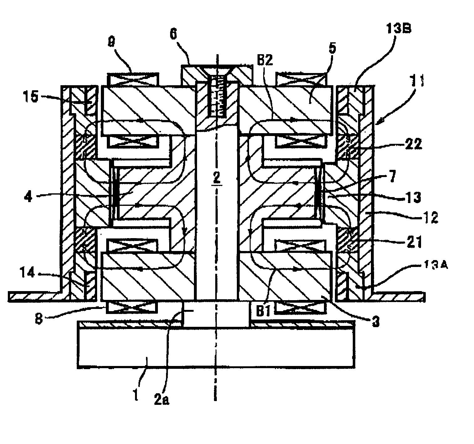
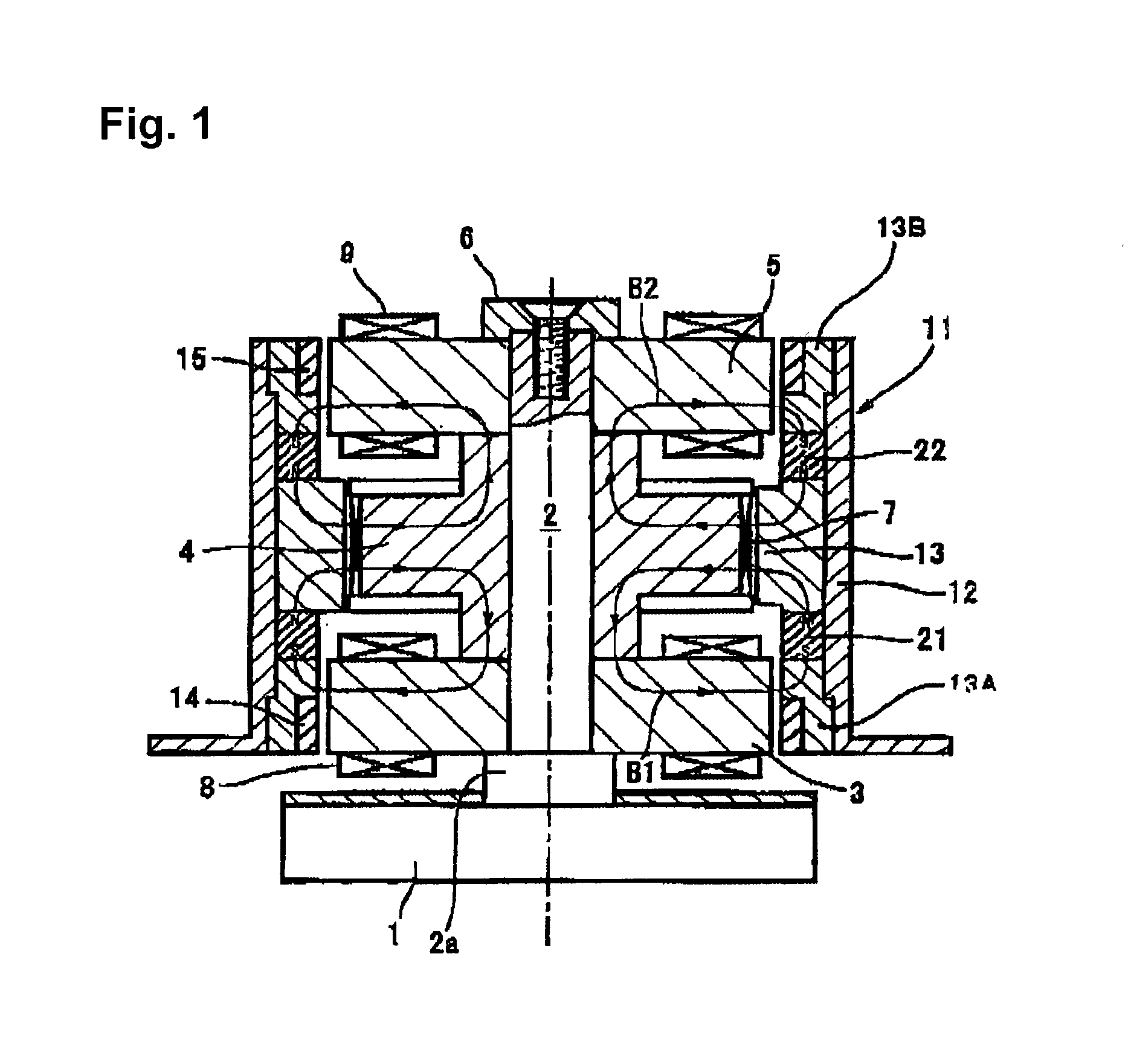
[0040] As described above, in the first embodiment shown in FIG. 1, a magnetically levitating motor that is formed from a compound structure of a radial magnetic bearing and a motor is provided with a rotor side thrust bearing magnetic path section and a stator side thrust bearing magnetic path section disposed opposite in the radial direction to the rotor side thrust bearing magnetic path section. Bias magnetic fluxes B1 and B2, which form radial levitation control fluxes, are arranged to pass the thrust control coil 7 in a voice coil motor (VMC) system disposed between the rotor side thrust bearing magnetic path section and the stator side thrust bearing magnetic path section. With the structure described above, and by circulating a current through the thrust control coil 7, the thrust bearing load is supported. Therefore, the thrust magnetic bearing can also be formed into a compound structure with the magnetically levitating motor that has a compound structure of a radial magnet...

second embodiment

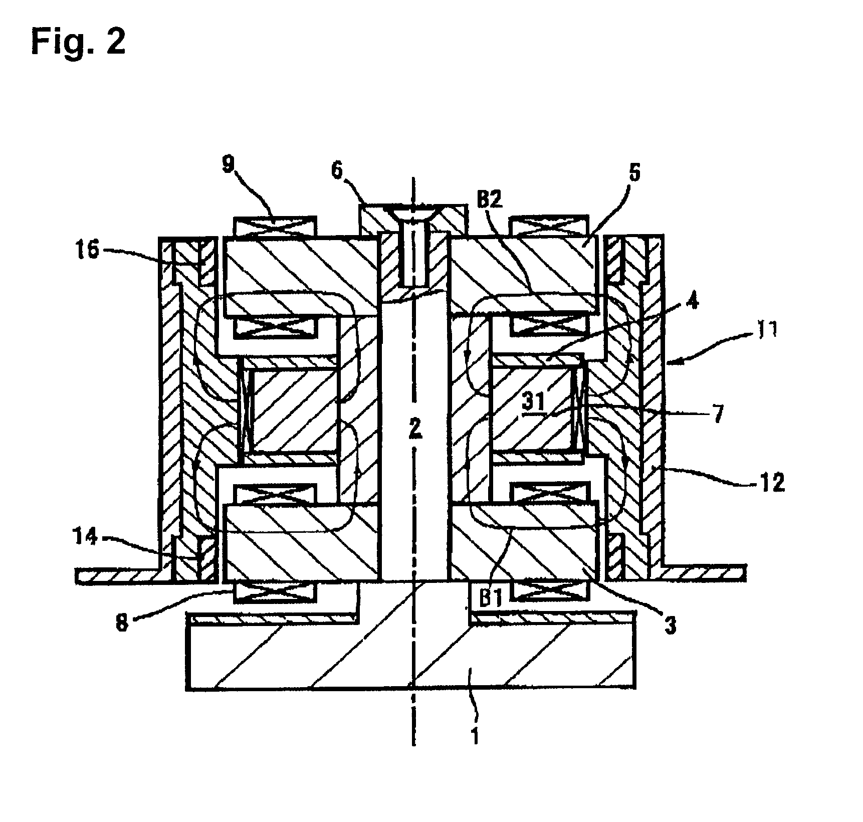
[0043] In accordance with the present invention shown in FIG. 2, a bias magnet 31 that forms bias magnetic fluxes B1 and B2 is disposed within the stator yoke 4 on the stator side. This embodiment can provide effects and functions similar to those of the embodiment described above.

[0044] FIG. 3 shows a hybrid type magnetic bearing apparatus in which the present invention is applied.

[0045] As indicated in FIG. 3, a rotor 42 is rotatably supported on the inside of a stator core 41 that is in a generally cylindrical form. The rotor 42 has a rotary shaft 43. A first rotor yoke 44, a center rotor yoke 45 and a second rotor yoke 46 are successively disposed along the rotary shaft 43 in the axial direction. The center rotor yoke 45 is formed from a generally cylindrical member in a coil bobbin shape, which forms a rotor side thrust bearing magnetic path section. A thrust control coil 47, which is wound about the rotary shaft as a center, is disposed on an outer circumferential section of t...


PUM


Abstract

A magnetically levitating motor includes a rotor that is formed from a magnetic material and has a permanent magnet attached along a circumference thereof, and a stator core section having a first stator coil that generates a levitation control magnetic flux that controls levitation of the rotor in a radial direction and a second coil that generates rotational magnetic flux against the rotor. In one aspect of the present invention, a rotor side thrust bearing magnetic path section is formed on the rotor, and a stator side thrust bearing magnetic path section that is disposed opposite in the radial direction to the rotor side thrust bearing magnetic path section is provided on the stator. A bias magnetic flux that forms the radial levitation control magnetic flux is formed to pass a gap in the radial direction between the rotor side thrust bearing magnetic path section and the stator side thrust bearing magnetic path section. A thrust control coil that generates a supporting force to support the thrust bearing load is disposed in the bias magnetic flux that forms the radial levitation control magnetic flux, wherein the thrust control coil is wound about a rotational axis with respect to one of the rotor side thrust bearing magnetic path section and the stator side thrust bearing magnetic path section.

Description

[0001] 1. Field of the Invention[0002] The present invention relates to a magnetically levitated motor and magnetic bearing apparatus equipped with a radial magnetic bearing and a thrust magnetic bearing that levitates and controls a rotor.[0003] 2. Description of Related Art[0004] Bearing apparatuses that are widely used in various equipment include, in addition to common contact type bearing apparatuses, magnetic bearing apparatuses that use magnetic force to levitate a rotary body such as a rotor shaft, and supports the rotary body in a non-contact matter. With a magnetic bearing apparatus, the coefficient of friction at its bearing sections is nearly zero, and thus a high speed rotation of the rotary body becomes possible. Also, since magnetic bearing apparatuses do not require lubricating oil, they can be used in special environments such as at high temperatures, lower temperatures or in vacuum, and are advantageous in that no maintenance is required.[0005] In view of the advan...

Claims


Application Information

Patent Timeline
IPC IPC(8): F16C39/06F16C32/04H02K7/09H02K21/22H02K33/18
CPCF16C32/0459F16C32/0493H02K7/09H02K21/22F16C2380/26
Inventor KANEBAKO, HIDEKI
Owner NIDEC SANKYO CORP
Why Eureka
Try Eureka