Synchronous motor driving system and sensorless control method for a synchronous motor

a synchronous motor and control method technology, applied in the direction of motor/generator/converter stopper, electronic commutator, dynamo-electric converter control, etc., can solve the problems of electromagnetic noise increase, significant reduction in the efficiency of synchronous motor, and vibration of transitory parts

Inactive Publication Date: 2003-03-27
HITACHI LTD
View PDF0 Cites 48 Cited by
  • Summary
  • Abstract
  • Description
  • Claims
  • Application Information

AI Technical Summary

Problems solved by technology

However, if a load is suddenly changed during driving, transient vibration may occur.
A similar problem is inherent in the method described in JP-A-8-308286.
In this method, however, since it is necessary to superpose the higher harmonic wave, a pulsation component is generated in a synchronous motor current, causing a considerable reduction in efficiency of the synchronous motor.
In addition, because of the superposed wave, electromagnetic noise is increased.
Especially, to detect an axial error with high sensitivity, the amount of superposed waves to be injected must be increased, and thus it is difficult to solve the above-described problems, and achieve high control performance at the same time.
In addition, since the saliency of the synchronous motor is used, the system cannot be applied to a synchronous motor of a non-saliency type.
Further, when the low-speed system, and the middle / high speed system are used in association, the systems must be switched according to a speed, and thus shocks occur following the switching.
However, in the V / F control, since the d-q axis in the synchronous motor is not basically coincident with the dc-qc axis on control, it is difficult to achieve high-performance control.
For example, it is difficult to achieve high-speed response to a change in a rotational speed command, linear control of torque, maximum efficiency control and the like.
Accordingly, there is a possibility that external disturbances such as fluctuation in load torque may cause inconveniences such as vibration or excessive current.

Method used


Image

  • Synchronous motor driving system and sensorless control method for a synchronous motor
  • Synchronous motor driving system and sensorless control method for a synchronous motor
  • Synchronous motor driving system and sensorless control method for a synchronous motor

Examples


first embodiment

[0049] First Embodiment

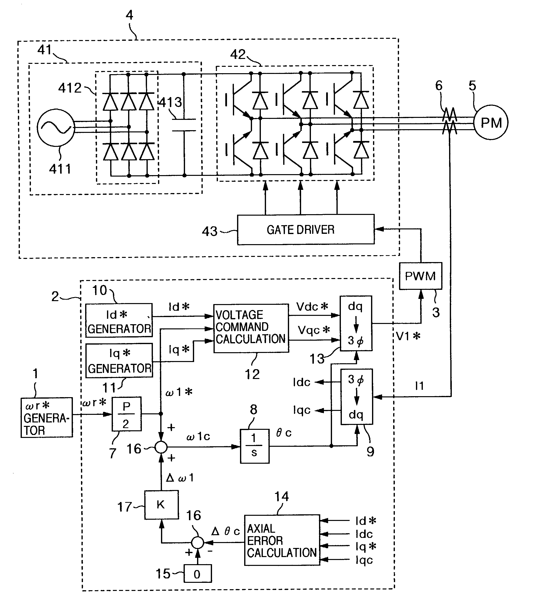
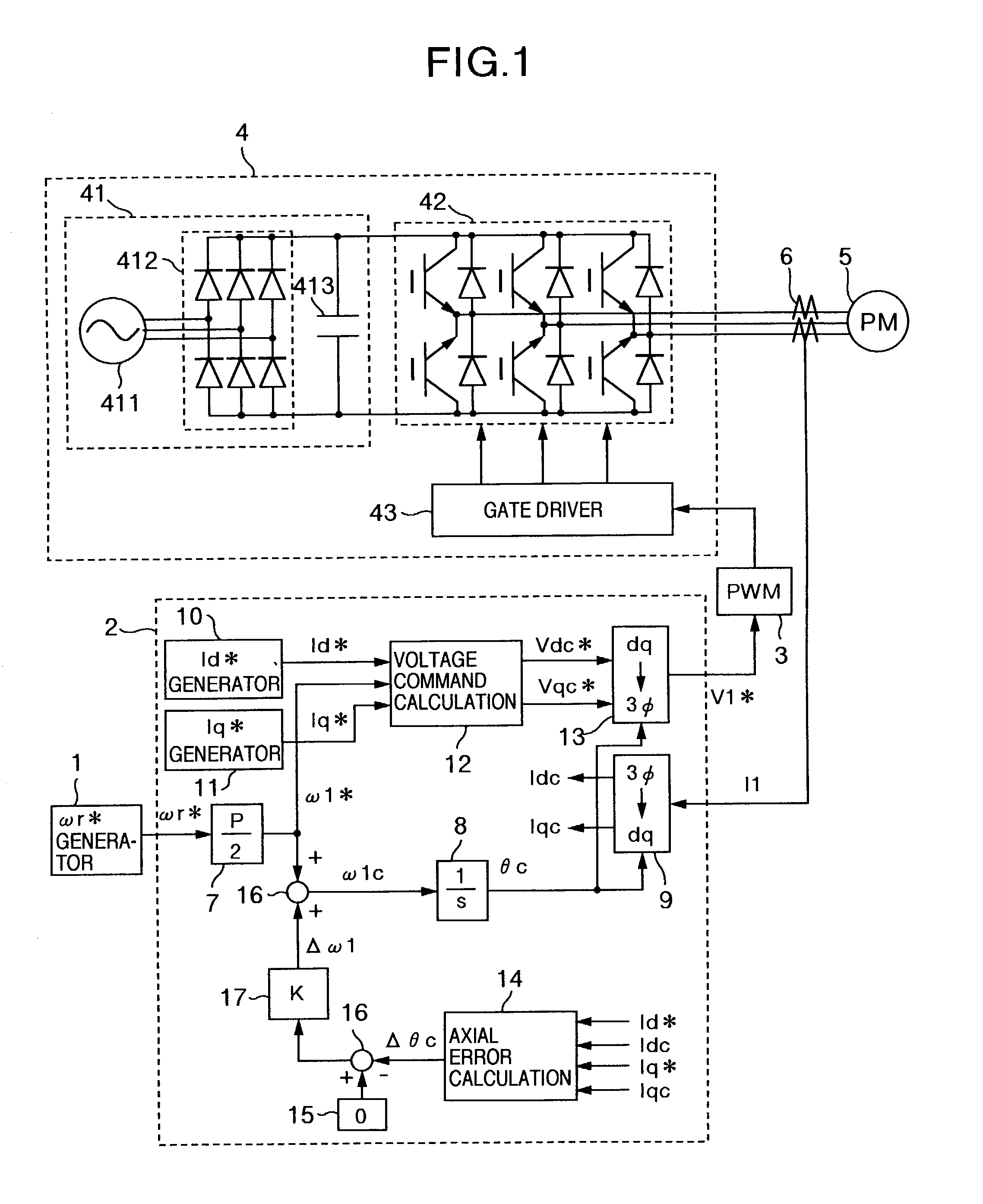
[0050] FIG. 1 is a block diagram showing a configuration of a synchronous motor driving system according to a first embodiment of the present invention. The synchronous motor driving system of the first embodiment comprises the following elements: a rotational speed command generator 1 for supplying a rotational speed command .omega.r* to the synchronous motor; a control unit 2 for calculating amplitude, a frequency and a phase of a voltage applied to the synchronous motor; a pulse width modulation (PWM) generation 3 for generating a pulse for driving an inverter 4 based on a voltage command V1*; the inverter 4 for driving the synchronous motor: the synchronous motor 5 to be controlled; a current detector 6 for detecting a current of the synchronous motor 5; a conversion gain 7 for converting the rotational speed command .omega.r* into an electrical angle frequency command .omega.1* of the synchronous motor with P set as a pole; an integrator 8 for calculating...

second embodiment

[0076] Second Embodiment

[0077] FIG. 5 is a block diagram showing a configuration of a synchronous motor driving system according to a second embodiment of the present invention. The synchronous motor driving system of the second embodiment includes an inverter 4B, a DC current detector 44 for detecting a current I0 flowing from a DC power supply unit 41 to an inverter main circuit unit, and a synchronous motor current estimator 18 for estimating a synchronous motor current based on a detected value of the current I0.

[0078] In the second embodiment of FIG. 5, the current detector 6 is removed from the configuration of the system shown in FIG. 1, and instead the DC current detector 44, and the synchronous motor current estimator 18 are added. The DC current detector 44 detects a current by using HALL CT or shunt resistance. The synchronous motor current estimator 18 estimates a synchronous motor current based on the detected value of the current IO, and a pulse waveform outputted from...

third embodiment

[0094] Third Embodiment

[0095] The above-described second embodiment enables the number of current sensors to be reduced, and thus provides an advantage of simplifying the configuration of the control system. However, the following problems are inherent. That is, when a rotational speed of the synchronous motor is low, and an output voltage is small, the periods of the modes 2 and 3 shown in FIG. 6 become short, necessitating reading of a very narrow pulse-like current. Waveforms in FIG. 6 are for principle explanation, and I0 represents a staircase having no vibration. In practice, however, ringing is superposed in a current waveform following switching. If a pulse width is narrow, this effect cannot be ignored.

[0096] FIG. 7 is a block diagram showing a configuration of a synchronous motor driving system according to a third embodiment of the present invention, which is provided to solve the problems of the second embodiment. The synchronous motor driving system of the third embodim...


PUM


Abstract

Axial error calculation unit is provided for estimating an axial error DELTAtheta between a d-q axis and a dc-qc axis by using Ld, Lq, Ke, Id*, Iq*, Idc and Iqc in a range of all rotational speeds except zero of a rotational speed command of a synchronous motor, Ld denoting an inductance on a magnetic pole axis d of the synchronous motor, Lq an inductance on a q axis orthogonal to the magnetic pole axis d, Ke a generated power constant of the motor, Id* a current command of the d axis, Iq* a current command on a q axis, Idc a detected current value on an assumed dc axis on control, and Iqc a detected current value on an assumed qc axis orthogonal to the assumed dc axis. Irrespective of presence of saliency, position sensorless control can be achieved in a wide range a low to high speed zone.

Description

[0001] 1. Field of the Invention[0002] The present invention relates to a synchronous motor driving system, and more particularly, it relates to a control method for achieving a highly precise and high-performance synchronous motor driving system without using any sensors for detecting a rotational speed of a synchronous motor and a position of a magnetic pole.[0003] 2. Description of the Related Art[0004] Many developments have been made for a method for controlling a synchronous motor without detecting the rotational speed of the synchronous motor and the position of a magnetic pole. Such control methods are usually classified into two types.[0005] A first type is a control method based on speed / position sensor vector control of the synchronous motor. Instead of using the speed / position sensor, a magnetic pole position estimating instrument, and a speed estimating instrument are used. For example, a method is known, which is described in a document 1: "No. SPC-00-67: A New Positio...

Claims


Application Information

Patent Timeline
Patent Type & Authority Applications(United States)
IPC IPC(8): H02P6/18H02P6/06H02P6/08H02P6/182H02P21/00H02P21/04H02P21/05H02P21/14H02P21/18H02P21/22H02P21/24H02P23/03H02P23/04H02P23/14H02P23/16H02P23/18H02P27/04H02P27/08
CPCH02P6/001H02P6/205H02P21/0039H02P6/21H02P6/34H02P21/24
Inventor IWAJI, YOSHITAKAENDO, TSUNEHIROSAKAMOTO, KIYOSHITAKAKURA, YUHACHI
Owner HITACHI LTD
Why Eureka
Try Eureka